






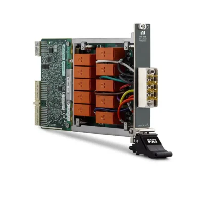
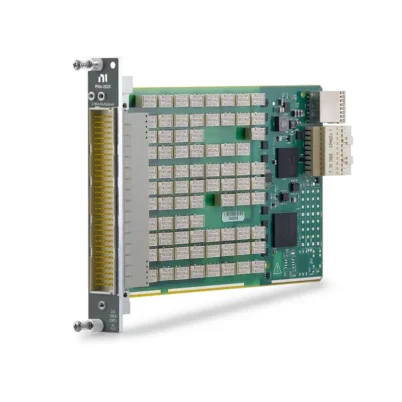
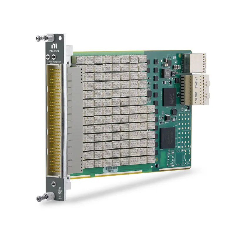
PXIe-2524 128-Channel 2 A Multibank PXI Multiplexer
Земля PXIe-2524 is a high-density, 1-wire PXI Express multiplexer switch module designed for automated test equipment, signal routing, production testing and electronic validation. Its 128 channels can be organized into one or multiple independently controlled multiplexer banks.
The module uses nonlatching electromechanical relays and supports signals up to 150 V, current up to 2 A and switching power up to 60 W or 62.5 VA. With a 10 MHz bandwidth, 1,000-cycle-per-second scan rate and five software-selectable topologies, the PXIe-2524 provides flexible routing for high-channel-count test systems.
Key Features of the PXIe-2524
- 128-channel, 1-wire PXI Express multiplexer
- Five software-selectable multibank topologies
- Sixteen banks of 8 × 1 multiplexers
- Eight banks of 16 × 1 multiplexers
- Four banks of 32 × 1 multiplexers
- Two banks of 64 × 1 multiplexers
- Single 128 × 1 multiplexer
- 150 V maximum switching voltage
- 2 A maximum switching and carry current
- 60 W or 62.5 VA maximum switching power
- 10 MHz typical bandwidth
- Less than 0.8 Ω initial DC path resistance
- Less than 10 µV thermal EMF
- 1,000 cycles/s scan rate
- Nonlatching electromechanical relays
- Onboard relay-count tracking
- Field-replaceable relays
- PXI hardware trigger support
- 160-position DIN front-panel connector
- NI-SWITCH and NI Switch Executive support
PXIe-2524 Technical Specifications
| Product Model | PXIe-2524 |
|---|---|
| Part Number | 780587-24 |
| Product Type | PXI Express multibank multiplexer switch module |
| Maximum Channel Count | 128 channels |
| Wire Mode | 1-wire |
| Supported Bank Counts | 1, 2, 4, 8 or 16 banks |
| Supported Topologies | 16-bank 8 × 1, 8-bank 16 × 1, 4-bank 32 × 1, 2-bank 64 × 1 and 128 × 1 |
| Maximum Switching Voltage | 150 VDC or 150 VAC |
| Measurement Category | CAT I/CAT O signal circuits |
| Maximum Switching Current | 2 A per channel |
| Maximum Carry Current | 2 A per channel |
| Maximum Switching Power | 60 W or 62.5 VA |
| Minimum Switch Load | 20 mV at 1 mA |
| Typical CH-to-COM DC Isolation | Greater than 1 GΩ at 25°C |
| Initial DC Path Resistance | Less than 0.8 Ω |
| End-of-Life Path Resistance | 1.8 Ω or greater |
| Thermal EMF | Less than 10 µV |
| Typical Bandwidth | Up to 10 MHz with 50 Ω termination |
| Scan Rate | 1,000 cycles/s |
| Typical Relay Operate Time | 1 ms |
| Maximum Relay Operate Time | 3.2 ms |
| Simultaneous Drive Limit | 90 relays |
| Mechanical Relay Life | 1 × 10⁸ cycles |
| Тип реле | Electromechanical, nonlatching |
| Relay Contact Material | Gold-covered palladium-ruthenium |
| Relay Serviceability | Field replaceable |
| Front-Panel Connector | 160-position male DIN 41612 |
| Шинный интерфейс | PXI Express |
| Module Format | 3U, one-slot PXI Express module |
| Dimensions | 21.6 × 2.0 × 13.0 cm |
| Weight | 241 g |
| Power Requirement | 24 W at 12 V and 3.4 W at 3.3 V |
| Поддержка программного обеспечения | NI-SWITCH and NI Switch Executive |
PXIe-2524 Part Number and Accessories
| Item | Part Number | Описание |
|---|---|---|
| PXIe-2524 | 780587-24 | 128-channel, 2 A, 1-wire multibank PXI Express multiplexer |
| 160-Pin DIN to Bare-Wire Cable | 782417-01 | Cable for connecting the module to a custom test fixture |
| 160-Pin DIN to 160-Pin DIN Cable | 782417-02 | Cable for compatible DIN-to-DIN switch connections |
| 160-Pin DIN to Four 50-Pin D-Sub Cable | 782417-03 | Breakout cable for connecting the module to compatible 50-pin terminal blocks |
| TBX-50 Terminal Block | 779305-01 | 50-pin remote terminal block for external signal wiring |
| TBX-50B Terminal Block | 782866-01 | Updated 50-pin remote terminal block for field wiring |
The PXIe-2524 uses a 160-position DIN front-panel connector. Select the cable and terminal-block combination according to the required topology, number of banks, fixture layout, voltage rating and signal count.
Configurable Multibank Multiplexer Architecture
The PXIe-2524 contains 128 one-wire channels that can be divided into several independently controlled multiplexer banks. Changing the topology is performed through software and does not require replacing a terminal block.
A larger number of banks allows several measurement instruments or test operations to run in parallel. Combining the channels into fewer banks increases the number of channels accessible from each common connection.
Sixteen Banks of 8 × 1 Multiplexers
In the 16-bank configuration, the PXIe-2524 operates as sixteen independent 8 × 1 multiplexers. Each bank connects one of eight channels to its corresponding common terminal.
This topology is useful for parallel test systems containing several instruments or groups of eight related test points. Each bank can be controlled separately without combining all 128 channels into one measurement sequence.
Eight Banks of 16 × 1 Multiplexers
The 8-bank topology organizes the module as eight independent 16 × 1 multiplexers. It balances parallel operation with a larger number of channels in each bank.
This configuration can support eight instruments, measurement groups or fixture sections when each group requires access to as many as 16 channels.
Four Banks of 32 × 1 Multiplexers
The 4-bank configuration provides four independent 32 × 1 multiplexers. Each bank routes one of 32 channels to a separate common connection.
It is well suited to production systems that need four parallel signal-routing groups while retaining substantial channel density within each group.
Two Banks of 64 × 1 Multiplexers
In the dual-bank topology, the PXIe-2524 operates as two independent 64 × 1 multiplexers. Two instruments can each access a group of 64 channels.
This arrangement can improve throughput when two measurement operations run in parallel or when the test fixture is divided into two independent sections.
Single 128 × 1 Multiplexer
The 128 × 1 topology combines all channels into one high-density multiplexer. One common terminal can be connected to any of the 128 input channels.
This configuration is useful for expanding a digital multimeter, digitizer, source or other instrument across many test points while occupying only one PXI Express chassis slot.
1-Wire Signal Routing
The PXIe-2524 switches one conductor for each selected channel. It is suitable for signals that share an external reference or return connection.
Because the module does not switch a separate return conductor for every channel, NI does not recommend it for 2-wire resistance measurements. Use a 2-wire or 4-wire multiplexer when both sides of the measurement circuit must be switched.
150 V Switching Capability
The module can switch signals up to 150 V between channels and up to 150 V from a channel to ground. It is rated for Measurement Category I/CAT O signal circuits.
The PXIe-2524 must not be connected directly to building mains or Measurement Category II, III or IV circuits. When hazardous voltage is present on any channel, safety-low-voltage signals must not be connected to other channels on the module.
2 A Switching and Carry Current
The PXIe-2524 supports switching and carry current up to 2 A per channel. This allows it to route general-purpose signals and moderate-current loads that exceed the capability of many high-density multiplexer modules.
Current must remain within the ratings of the module, cable, terminal block and fixture wiring. The common terminal and external connector path must also be evaluated for the expected load.
60 W and 62.5 VA Switching Power
The maximum switching power is 60 W for DC loads and 62.5 VA for applicable AC loads. Voltage, current and power ratings must all be observed simultaneously.
The full 2 A current rating cannot be switched at 150 V because the resulting power would exceed the module’s 60 W limit. Calculate the actual voltage-current product before connecting the load.
Low DC Path Resistance
Initial DC path resistance is specified at less than 0.8 Ω. Path resistance includes relay contact resistance and the internal circuit traces between the selected channel and common terminal.
Path resistance can produce voltage drop and power dissipation when routing higher current. Cable, terminal-block and test-fixture resistance must also be included in the complete signal-path calculation.
Low Thermal EMF
The PXIe-2524 provides thermal EMF below 10 µV. Low thermal offset helps reduce errors when switching low-level DC voltage and measurement signals.
For microvolt-level measurements, also consider connector materials, cable temperature gradients, relay settling, grounding and the thermal characteristics of the external fixture.
10 MHz Typical Bandwidth
The module provides typical bandwidth up to 10 MHz with 50 Ω termination. This supports DC, low-frequency and moderate-frequency signal routing in automated test systems.
Actual system bandwidth depends on the selected topology, cable length, source impedance, load impedance, closed-channel configuration and fixture construction.
Fast 1,000-Cycle-per-Second Scanning
The PXIe-2524 supports scanning at up to 1,000 cycles per second. Its fast operation is useful for high-throughput production systems and automated measurement sequences containing many test points.
Total completed-test rate also depends on relay settling, instrument measurement time, trigger configuration, software execution and device-under-test stabilization.
Nonlatching Electromechanical Relays
The module uses nonlatching electromechanical relays with gold-covered palladium-ruthenium contacts. These relays provide physical contact isolation and support a wide range of DC and AC signals.
Nonlatching relays return to their default state when power is removed. Test-system designers should confirm that the default state provides the required behavior during chassis shutdown or controller failure.
Relay Life and Replaceability
The expected mechanical relay life is 100 million cycles. Electrical life depends on the switched voltage, current and load type.
NI specifies approximately 2.5 million operations for a low-level load of 30 mV or less and 10 mA or less, 500,000 operations at 30 V and 1 A, and 100,000 operations at 30 V and 2 A.
The relays are field replaceable. Relay-count data and resistance testing can help identify heavily used or deteriorating channels before they cause unexpected system downtime.
Onboard Relay-Count Tracking
The PXIe-2524 records how often its relays operate. These counts can be retrieved programmatically to identify heavily used paths and assist with preventive maintenance.
When the test architecture allows, high-use routes can be distributed across several banks or channels to balance relay wear.
Hardware Triggering
PXI hardware triggers can coordinate channel changes with digital multimeters, data acquisition modules, digitizers and other PXI instruments. The instrument can initiate the next switch operation after completing a measurement.
Hardware synchronization reduces software timing overhead and helps achieve repeatable, deterministic scanning in automated test applications.
Typical PXIe-2524 Applications
- Автоматизированное испытательное оборудование
- Digital multimeter channel expansion
- Production functional testing
- Printed circuit board testing
- Electronic device validation
- General-purpose signal routing
- Multichannel voltage measurement
- Parallel instrument switching
- Sensor measurement systems
- Design verification testing
- Reliability and environmental testing
- Laboratory automation
Digital Multimeter Channel Expansion
The PXIe-2524 can expand one or more digital multimeters across many voltage or continuity test points. Software selects a channel, allows the route to settle and then commands the instrument to acquire a measurement.
The 128 × 1 topology maximizes the number of points accessible to one instrument, while the multibank configurations support parallel operation with several instruments.
Parallel Automated Measurements
The multibank architecture allows several instruments to access independent channel groups at the same time. This can reduce total test time compared with routing every signal through one common connection.
For example, the four-bank topology can assign separate 32-channel groups to different measuring instruments or fixture sections.
Production Test Systems
Production systems can use the PXIe-2524 to route measurement, stimulus and control signals without manual cable changes. Its high channel density reduces the number of switch modules required in a PXI Express chassis.
Fast scanning, hardware triggering and relay-count tracking support high-throughput systems that require repeatable operation and planned maintenance.
NI-SWITCH Software Support
The PXIe-2524 is controlled through the NI-SWITCH instrument driver. NI-SWITCH provides functions for selecting a topology, connecting channels, creating scan lists, routing hardware triggers and reading relay-count information.
The driver supports LabVIEW, LabWindows/CVI and compatible text-based programming environments. The correct topology must be selected before channel routes are configured.
NI Switch Executive Integration
NI Switch Executive allows physical channel and common-terminal names to be replaced with descriptive signal aliases. Developers can create named routes and route groups corresponding to instruments, fixtures and device-under-test connections.
This simplifies test programs containing several banks, instruments or PXI switch modules and makes fixture changes easier to manage.
PXI Express Chassis Integration
The PXIe-2524 occupies one 3U PXI Express slot. It can operate alongside digital multimeters, oscilloscopes, digitizers, data acquisition modules, power supplies and other PXI Express instruments.
Before installation, verify the chassis slot compatibility, power and cooling capacity, controller support and required NI-SWITCH version. Turn off chassis power before installing or removing the module.
PXIe-2524 Troubleshooting
The PXIe-2524 is not detected in NI MAX
Confirm that the module is fully installed in a compatible PXI Express slot. Check chassis power, controller communication and NI-SWITCH installation, then rescan the system in NI Measurement & Automation Explorer.
A requested channel cannot be connected
Verify that the channel name is valid for the selected topology. Changing between 16-bank, 8-bank, 4-bank, 2-bank and single-bank operation changes the available channel and common-terminal structure.
The wrong bank is connected
Review the NI-SWITCH topology, channel aliases and external connector wiring. Confirm that the selected common terminal corresponds to the intended bank.
The signal path has excessive resistance
Inspect the cable, terminal block, connector and fixture wiring. Compare the measured resistance with the initial module path specification and review the relay operation count for the affected channel.
Measurements change after channel switching
Add sufficient settling time after operating the relay. Check source impedance, cable capacitance, thermal offsets, grounding and the measurement instrument’s input characteristics.
The scan rate is lower than expected
Review measurement aperture, settling delay, trigger timing and software processing. The specified scan rate does not include every delay in the complete measurement sequence.
A relay appears to be worn or stuck
Use NI-SWITCH diagnostics and relay-count information to check the affected path. The PXIe-2524 uses field-replaceable relays, but service must follow the applicable NI replacement procedure.
The module becomes unusually warm
Stop the test and check load current, simultaneous relay operation, chassis airflow and fan settings. Confirm that the connected circuits remain within the voltage, current and switching-power limits.
PXIe-2524 Comparison with Similar Multiplexer Modules
| Модель | Primary Configuration | Best Suited For |
|---|---|---|
| PXIe-2524 | Up to 128 channels, 1-wire, multibank, 150 V, 2 A | High-density common-reference signal routing |
| PXIe-2525 | Up to 64 channels, 2-wire, multibank, 150 V, 2 A | Differential signals and switched return paths |
| PXIe-2526 | 158-channel 1-wire or 79-channel 2-wire multiplexer | Maximum channel density in a single bank |
| PXIe-2527 | Up to 64 one-wire channels, 300 V, 2 A | Higher-voltage and multiwire measurements |
| PXIe-2575 | Up to 196 one-wire channels, 100 V, 1 A | Very-high-channel-count signal routing |
PXIe-2524 vs PXIe-2525
The PXIe-2524 switches one conductor per channel and provides as many as 128 channels. The PXIe-2525 switches two conductors together and provides as many as 64 2-wire channels.
Choose the PXIe-2524 for common-reference measurements requiring maximum channel density. Choose the PXIe-2525 when both the signal and return conductors must be switched.
PXIe-2524 vs PXIe-2526
The PXIe-2524 provides configurable multibank operation, allowing as many as 16 independent multiplexers. The PXIe-2526 provides a larger single-bank channel count with 158 one-wire or 79 two-wire channels.
Select the PXIe-2524 when several instruments or fixture sections must operate in parallel. Select the PXIe-2526 when one instrument must access the highest possible number of channels.
PXIe-2524 vs PXIe-2527
The PXIe-2524 provides up to 128 one-wire channels, 150 V switching and multibank operation. The PXIe-2527 supports fewer channels but provides 300 V capability and 1-wire, 2-wire and 4-wire topologies.
Choose the PXIe-2524 for higher channel density and parallel banks. Choose the PXIe-2527 when higher voltage or multiwire resistance and differential measurements are required.
Recommended Related Products
- PXIe-2525 64-Channel 2-Wire Multibank Multiplexer
- PXIe-2526 158-Channel Multiplexer Switch Module
- PXIe-2527 300 V Multiplexer Switch Module
- PXIe-2575 High-Density Multiplexer Switch Module
- PXIe-4080 Digital Multimeter
- View More NI PXI and PXI Express Modules
Selecting the Right PXI Multiplexer
Choose the PXIe-2524 when the application requires as many as 128 one-wire channels, several independently controlled banks, 2 A switching and software-selectable topology changes. It is well suited to common-reference measurements and parallel automated test systems.
Select the PXIe-2525 when two conductors must be switched together, the PXIe-2526 when maximum single-bank density is required or the PXIe-2527 when the application needs higher voltage and 2-wire or 4-wire operation.
Why Choose the PXIe-2524?
- Provides as many as 128 one-wire channels
- Supports five software-selectable multibank configurations
- Allows as many as 16 independent multiplexer banks
- Switches signals up to 150 V and 2 A
- Offers 10 MHz typical bandwidth
- Scans at up to 1,000 cycles per second
- Uses field-replaceable electromechanical relays
- Includes onboard relay-count tracking
- Supports deterministic PXI hardware triggering
- Integrates with NI-SWITCH and NI Switch Executive
Frequently Asked Questions
What is the PXIe-2524?
The PXIe-2524 is a 128-channel, 1-wire, multibank PXI Express multiplexer switch module for automated signal routing.
Which topologies does the PXIe-2524 support?
It supports sixteen 8 × 1 banks, eight 16 × 1 banks, four 32 × 1 banks, two 64 × 1 banks or one 128 × 1 multiplexer.
Can the topology be changed through software?
Yes. The five multiplexer configurations are selected through software without changing the module or installing a different topology terminal block.
What is the maximum switching voltage?
The maximum switching voltage is 150 V between channels or between a channel and ground for CAT I/CAT O signal circuits.
What is the maximum switching current?
The module supports switching and carry current up to 2 A per channel.
What is the maximum switching power?
Maximum switching power is 60 W or 62.5 VA. Voltage, current and power limits must all be observed simultaneously.
What is the bandwidth of the PXIe-2524?
The typical switch bandwidth is up to 10 MHz with 50 Ω termination.
Can the PXIe-2524 be used for 2-wire resistance measurements?
NI does not recommend the PXIe-2524 for 2-wire resistance measurements because it switches only one conductor. Consider the PXIe-2525 or another multiwire multiplexer instead.
Are the relays replaceable?
Yes. The PXIe-2524 uses field-replaceable electromechanical relays when serviced according to the applicable NI procedure.
Which cables are compatible with the PXIe-2524?
Compatible choices include the 782417-01 bare-wire cable, 782417-02 DIN-to-DIN cable and 782417-03 DIN-to-four-D-Sub breakout cable.
Which software controls the PXIe-2524?
The module is controlled through NI-SWITCH and can be incorporated into named-route systems using NI Switch Executive.
What is the PXIe-2524 part number?
The standard NI part number is 780587-24.
Request a Quote for the PXIe-2524
Contact us for current availability, lead time and project pricing for the PXIe-2524 128-Channel 2 A Multibank PXI Multiplexer Switch Module. We can also help identify compatible 160-pin DIN cables, TBX-50 terminal blocks, PXI Express chassis and related NI multiplexer modules for your automated test system.















