






Ballard ARINC 429 Avionics Databus Interfaces
Ballard ARINC 429 interfaces are avionics communication products designed for monitoring, transmitting, recording, simulating and validating commercial and military aircraft databuses. Available platforms include PXI Express, PCI Express, PCI, USB, Ethernet-connected appliances and embedded interface cards.
Depending on the selected product, Ballard hardware can provide one to 16 or more ARINC 429 receive and transmit channels. Configurable channels can be programmed as receivers or transmitters, while advanced versions add error injection, waveform parameter control and physical-layer testing.
Ballard products are supplied under Astronics Ballard Technology. Major product families include OmniBus II modular PXIe and PCIe cards, OmniBusBox II Ethernet and USB appliances, UA2000 and USB 429 portable interfaces, Lx5 computer interface cards and ME1000 embedded modules.
This page covers the general Ballard ARINC 429 series. The exact channel count, receive/transmit arrangement, ARINC 717 support, parametric capability, connector, platform and part number depend on the selected configuration.
Key Features of Ballard ARINC 429 Interfaces
- ARINC 429 receive and transmit capability
- Programmable receive/transmit channel options
- Fixed receive and transmit channel configurations
- Support for standard low- and high-speed ARINC 429 operation
- Continuous message monitoring and timestamping
- Programmable transmit schedules
- Message recording and playback
- Label, SDI, data, SSM and parity decoding
- Protocol error generation on supported hardware
- Advanced parametric waveform control options
- ARINC 717 compatibility on selected modules
- Serial and discrete I/O combinations
- PXI Express interface cards
- PCI Express and PCI interface cards
- Portable USB interfaces
- Ethernet and USB OmniBusBox II appliances
- IRIG, 10 MHz and PPS timing options
- Programmable triggers and synchronization
- BTIDriver programming support
- CoPilot test and analysis software support
Ballard ARINC 429 Product Platforms
| Product Family | Host Interface | Typical ARINC 429 Capability | Best Suited For |
|---|---|---|---|
| OmniBus II PXIe | PXI Express | Up to 16 configurable or advanced fixed R/T channels per module | Modular avionics test and simulation systems |
| OmniBus II PCIe | PCI Express | Configurable multiprotocol two-core architecture | Desktop and rackmount computers |
| OmniBusBox II | Ethernet, USB or standalone | Two- or four-core multiprotocol appliance | Networked laboratory and field testing |
| UA2000 | SuperSpeed USB 3.1 | Portable multiprotocol receive and transmit channels | Modern portable avionics testing |
| USB 429/717 | USB 2.0 | 1R/1T through 12R/4T configurations | Flight-line and portable laboratory testing |
| Lx5 ARINC 429/717 | PCIe or PCI | Dedicated computer interface cards | Fixed production and development systems |
| ME1000 | Mini PCI Express | Up to 8R/4T with selected ARINC 717 support | Rugged embedded integration |
| USB Interface PCBA | Embedded USB | No-enclosure version of portable interfaces | Low-power embedded applications |
ARINC 429 Technical Overview
| Characteristic | Описание |
|---|---|
| Protocol Type | Unidirectional point-to-point avionics databus |
| Physical Medium | Shielded twisted-pair differential wiring |
| Standard Data Rates | 12.5 kbit/s low speed and 100 kbit/s high speed |
| Word Length | 32 bits |
| Encoding | Bipolar return-to-zero |
| Transmission Direction | One transmitter to one or more receivers |
| Label | 8 bits |
| Source/Destination Identifier | 2 bits |
| Data Field | 19 bits, with certain formats using part of the field for additional functions |
| Sign/Status Matrix | 2 bits |
| Parity | 1 bit, normally odd parity |
| Word Gap | Minimum interval between transmitted words as defined by the applicable specification |
| Common Data Formats | BNR, BCD, discrete and maintenance data |
ARINC 429 Receive Operation
A Ballard ARINC 429 receiver monitors the differential signal from an avionics transmitter and converts each valid waveform into a decoded 32-bit word.
Software can filter received traffic by label, SDI or other word fields. Each message can be timestamped and stored for display, analysis, recording or automated test evaluation.
Multiple receivers allow one test system to monitor several independent ARINC 429 buses simultaneously.
ARINC 429 Transmit Operation
An ARINC 429 transmitter sends 32-bit words on one dedicated output pair. Ballard hardware can transmit individual words or execute repeating schedules with programmable update rates.
Transmit channels can simulate aircraft sensors, flight-control computers, navigation equipment and other line-replaceable units.
The test application can modify selected labels or data values while the remaining scheduled messages continue transmitting.
Programmable Receive and Transmit Channels
Selected OmniBus II modules provide channels that can be configured as receivers or transmitters. This allows one hardware configuration to support different test fixtures and equipment types.
Module 441 provides eight configurable receive/transmit ARINC 429 channels, while module 442 provides 16 configurable channels.
The required number of transmitters and receivers should be determined before configuring the card because a channel assigned for transmission is no longer available as a receiver.
Fixed Receive and Transmit Channels
Other Ballard modules use a fixed receive/transmit arrangement, such as 4R/4T or 8R/8T. These configurations guarantee a specific number of receivers and transmitters.
Fixed arrangements are useful when the test requirements are known and advanced transmitter functions must be available on every transmit channel.
Advanced Parametric Control
Advanced ARINC 429 modules can vary selected physical-layer and protocol characteristics for equipment-margin and fault-response testing.
Supported capabilities can include waveform amplitude adjustment, rise and fall time control, data-rate variation, word-gap modification and intentional protocol errors.
Parametric tests should be performed only in a controlled laboratory or production environment. The generated waveform may intentionally operate outside normal ARINC 429 limits.
Protocol Error Injection
Supported hardware can generate malformed or abnormal ARINC 429 transmissions to verify how receiving equipment detects and handles errors.
Test cases may include incorrect parity, invalid bit timing, abnormal word gaps, altered data rate and waveform conditions enabled by the selected interface.
Error injection is valuable for design validation, fault testing and certification-support activities in which normal traffic alone is insufficient.
OmniBus II ARINC 429 Module Numbers
| Module Number | ARINC 429 Configuration | Additional Capability |
|---|---|---|
| 441 | 8 configurable receive/transmit channels | Software-selectable channel direction |
| 442 | 16 configurable receive/transmit channels | High channel density |
| 454 | 4 receive and 4 transmit channels | Advanced parametric control |
| 455 | 4R/4T ARINC 429 | Advanced parametric control plus 4R/4T ARINC 717 |
| 456 | 4 receive and 4 transmit channels | Advanced parametric control plus four serial UARTs |
| 458 | 8 receive and 8 transmit channels | Advanced parametric control |
OmniBus II Platform Numbers
| Platform Number | Product Platform | Protocol Cores |
|---|---|---|
| 212 | OmniBus II PCI Express card | 2 |
| 222 | OmniBus II PXI Express card | 2 |
| 262 | OmniBusBox II Ethernet and USB appliance | 2 |
| 264 | OmniBusBox II Ethernet and USB appliance | 4 |
Understanding OmniBus II Part Numbers
OmniBus II part numbers combine a three-digit platform number with one module number for each protocol core. A two-core product therefore contains a platform code followed by two module codes.
For example, 222-441-000 identifies an OmniBus II PXIe card with eight configurable ARINC 429 channels in the first core and an unpopulated second core.
Part number 212-458-822 identifies an OmniBus II PCIe card with 8R/8T advanced ARINC 429 channels and 2R/2T parametric ARINC 708 channels.
Because hundreds of combinations are possible, the complete part number must be matched to the required platform, protocols and channel counts.
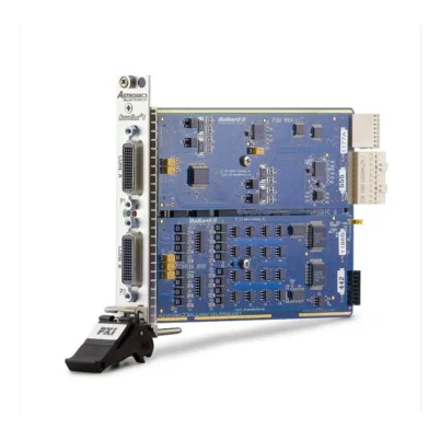
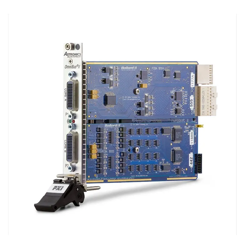
OmniBus II PXIe ARINC 429 Cards
The Ballard OmniBus II PXIe installs in a PXI Express or compatible CompactPCI Express test system. It provides two configurable protocol cores.
One core can contain an ARINC 429 module while the second can provide additional ARINC 429 channels, MIL-STD-1553, ARINC 708, serial communication or discrete I/O.
PXIe integration allows avionics messages to be synchronized with digitizers, waveform generators, switching modules, power supplies and other modular instruments.
OmniBus II PCIe ARINC 429 Cards
The Ballard OmniBus II PCIe provides the same modular two-core architecture for desktop and rackmount computers.
It is suitable for fixed development, production and simulation systems that do not require a PXI Express chassis.
Three synchronization inputs and three triggers are available per core on supported OmniBus II cards, together with advanced IRIG, 10 MHz and PPS timing resources.
OmniBusBox II ARINC 429 Interfaces
The Ballard OmniBusBox II is an external appliance controlled through Ethernet or USB. Supported configurations can also operate independently of the host computer.
Two-core and four-core models allow ARINC 429 to be combined with MIL-STD-1553, ARINC 708, ARINC 717, serial interfaces and discrete I/O.
OmniBusBox II is useful when the interface must be located near the aircraft equipment or accessed over a laboratory network.
Ballard USB 429 Interfaces
The Ballard USB 429 family provides portable ARINC 429 receive and transmit capability for Windows computers.
Available USB 2.0 configurations include 1R/1T, 4R/2T, 8R/4T and 12R/4T channel arrangements. Combination models also support ARINC 717.
USB interfaces are suitable for flight-line maintenance, laboratory development, troubleshooting and portable data-loading applications.
Ballard USB 429 Model Comparison
| Hardware Model | CoPilot Bundle | Channel Configuration |
|---|---|---|
| UA1410 | CP-UA1410 | 1 ARINC 429 receiver and 1 transmitter |
| UA1420 | CP-UA1420 | 4 ARINC 429 receivers and 2 transmitters |
| UA1430 | CP-UA1430 | 8 ARINC 429 receivers and 4 transmitters |
| UA1440 | CP-UA1440 | 12 ARINC 429 receivers and 4 transmitters |
| UA1431 | CP-UA1431 | 8R/4T ARINC 429 plus 2R/2T ARINC 717 |
| UA1401 | CP-UA1401 | 2R/2T ARINC 717 |
Ballard UA2000 USB 3.1 Interfaces
The Ballard UA2000 is a current-generation portable SuperSpeed USB avionics interface.
Depending on the model, the UA2000 can combine ARINC 429 with MIL-STD-1553, ARINC 708, ARINC 717, serial interfaces, avionics discrete I/O and timing resources.
It is suitable for engineers who need one portable interface for multiple commercial and military avionics protocols.
ARINC 429 and ARINC 717 Combination Interfaces
Selected Ballard modules provide both ARINC 429 and ARINC 717 channels. This is useful for systems containing general avionics communication and flight-data-acquisition interfaces.
OmniBus II module 455 provides 4R/4T advanced ARINC 429 and 4R/4T ARINC 717. USB model UA1431 provides 8R/4T ARINC 429 and 2R/2T ARINC 717.
On certain embedded products, ARINC 429 and ARINC 717 functions share physical pins. Enabling ARINC 717 can reduce the number of ARINC 429 channels available.
ME1000 Embedded ARINC Interfaces
Ballard ME1000 Mini PCI Express products provide ARINC 429 and ARINC 717 connectivity for embedded and rugged computing platforms.
Available channel combinations include 4R/4T, 6R/2T, 6R/4T, 8R/2T and 8R/4T ARINC 429, with selected ARINC 717 receive/transmit capability.
ME1000 ARINC Model Comparison
| Модель | ARINC 429 | ARINC 717 | Discrete I/O |
|---|---|---|---|
| ME1020 | 4R/4T | 1R/1T | 6 inputs and 2 outputs |
| ME1030 | 6R/2T | 1R/1T | 6 inputs and 2 outputs |
| ME1040 | 6R/4T | 1R/1T | 2 inputs and 2 outputs |
| ME1050 | 8R/2T | 1R/1T | 2 inputs and 2 outputs |
| ME1060 | 8R/4T | 1R/1T | No standard discrete I/O |
ARINC 429 Message Scheduling
Ballard transmitters can generate repeating message schedules with independent rates for different labels. Frequently updated flight-control data can be transmitted faster than maintenance or status information.
Scheduled transmission reduces the host computer’s timing burden because the interface hardware controls the precise sequence and word gaps.
Applications can update message data while the hardware continues executing the schedule.
ARINC 429 Monitoring and Filtering
Receiver filters allow software to select relevant labels or word patterns while ignoring unrelated bus traffic.
Filtering is useful in systems containing many labels and update rates. It can reduce host processing and simplify test-result evaluation.
A full bus-monitoring application can also record all received messages for later analysis.
Timestamping and Synchronization
Ballard hardware can timestamp received and transmitted data using internal timing resources. Eligible platforms support synchronization through IRIG, 10 MHz, pulse-per-second and programmable triggers.
Common timing allows ARINC 429 messages to be correlated with MIL-STD-1553 traffic, ARINC 717 data, analog measurements, video or other flight-test information.
Built-In Test
Supported OmniBus II products include power-up, initiated and continuous built-in-test functions. These diagnostics help verify memory, protocol engines and hardware operation.
Built-in test does not verify every external cable, connector or aircraft signal. The complete path should be tested separately.
BTIDriver Software Interface
BTIDriver provides the programming interface for compatible Ballard hardware. It allows applications to configure receivers, create transmit schedules, read messages, manage timestamps and control triggers.
A common API helps developers move applications between supported USB, PCIe, PXIe, Ethernet and embedded Ballard platforms.
Verify the driver version, operating system and hardware generation before installing an older interface in a newer test computer.
CoPilot Test and Analysis Software
Ballard CoPilot provides a graphical environment for monitoring, recording, replaying, analyzing and simulating ARINC 429 data.
Users can define engineering units, decode labels, display changing values, create transmit schedules and automate tests without developing a complete custom application.
CoPilot licenses are associated with specific Ballard hardware devices. Add the CP- prefix to an eligible OmniBus II configuration when ordering hardware with a CoPilot license.
ARINC 429 Cabling
ARINC 429 uses shielded twisted-pair wiring for each unidirectional channel. A transmitter output and receiver input must be connected with the correct polarity.
Ballard products use different high-density connectors according to platform and channel count. Breakout cables or mating connectors expose the individual receive and transmit pairs.
Before ordering, verify the interface connector, cable length, number of channels and whether discrete, serial or timing signals are required.
USB Interface Accessories
| Accessory | Part Number | Описание |
|---|---|---|
| ARINC 615-3 Data Loader Cable | 16080 | Connects a Ballard USB 429 interface to a 53-pin data-loader connector |
| ARINC 603 Adapter Cable | 16081 | Adapts the 53-pin ARINC 615-3 cable to a 31-pin ARINC 603 connector |
| USB 717 Aircraft Cable | 16078 | Connects a compatible USB 717 interface to a Boeing system-test plug |
ARINC 615 Data Loading
Selected Ballard USB 429 interfaces can be used with data-loader software and cables to load software or databases into compatible line-replaceable units.
Part number 16080 connects the interface to a standard ARINC 615-3 53-pin connector. Adapter 16081 converts this connection for compatible ARINC 603 equipment.
Typical Ballard ARINC 429 Applications
- Commercial avionics development
- Line-replaceable-unit simulation
- ARINC 429 bus monitoring
- Message recording and playback
- Production acceptance testing
- Hardware-in-the-loop testing
- System integration laboratories
- Flight-line maintenance
- Flight-test data acquisition
- Protocol compliance testing
- Error-response validation
- Physical-layer waveform testing
- Aircraft data loading
- Navigation-system testing
- Flight-control-system validation
- Display and instrument testing
Avionics Equipment Simulation
Transmit channels can reproduce labels and update rates normally generated by aircraft sensors, navigation systems and flight-control computers.
Receivers monitor responses or outputs from the equipment under test. This allows avionics units to be tested before the complete aircraft system is available.
Hardware-in-the-Loop Testing
PXIe and PCIe ARINC 429 interfaces can connect real avionics equipment to simulation models running in automated test systems.
ARINC 429 data can be synchronized with MIL-STD-1553, analog signals, discrete I/O and other simulated aircraft interfaces.
Production Acceptance Testing
Ballard interfaces can verify an avionics unit’s transmitted labels, data values, parity, update rates and electrical response during production testing.
Automated test sequences improve repeatability and allow message histories and results to be retained for traceability.
Flight-Line Troubleshooting
Portable USB interfaces allow technicians to monitor aircraft data or simulate an avionics transmitter using a notebook computer.
Recorded traffic can be reviewed in CoPilot to identify missing labels, incorrect update rates, parity errors or unexpected data values.
Ballard ARINC 429 Troubleshooting
The Ballard interface is not detected
Confirm that the correct BTIDriver version is installed. Check the PXIe, PCIe, PCI, USB or Ethernet connection and verify operating-system compatibility.
No ARINC 429 data is received
Check the receiver channel, wiring polarity, cable continuity and transmitter power. Confirm that the receiver speed matches the bus data rate.
Received words contain parity errors
Inspect wiring polarity, shielding, grounding and cable routing. Verify that intentional parity-error generation or parametric testing is disabled.
The decoded label appears incorrect
ARINC 429 labels use a bit-order convention that can appear reversed in raw binary displays. Confirm the display and decoding settings in the application.
The transmitter sends at the wrong speed
Verify whether the channel is configured for low-speed or high-speed operation. Check the transmit schedule and any enabled parametric data-rate adjustment.
Messages are transmitted at the wrong rate
Review the scheduled interval for each label. Make sure the host application is updating data rather than repeatedly recreating or stopping the schedule.
CoPilot cannot connect to the hardware
Verify that the device has the required CoPilot license key and that the CoPilot and BTIDriver versions support the interface.
A USB interface disconnects during operation
Try another USB port and cable, avoid unpowered hubs and disable unsupported USB power-saving settings. Confirm that the interface receives sufficient power.
OmniBusBox II cannot be found on the network
Check power, Ethernet link status, IP address, subnet and firewall settings. A direct Ethernet connection may be required for initial configuration.
Parametric changes have no effect
Verify that the installed module is 454, 455, 456 or 458 and supports advanced parametric control. Standard configurable modules 441 and 442 do not provide the same physical-layer functions.
ARINC 717 reduces the available 429 channel count
Some embedded interfaces share physical pins between ARINC 429 and ARINC 717. Review the selected operating mode and model-specific pin assignment.
Ballard ARINC 429 Platform Comparison
| Platform | Mobility | Protocol Flexibility | Recommended Use |
|---|---|---|---|
| OmniBus II PXIe | Rack or benchtop PXIe system | High | Integrated modular avionics testing |
| OmniBus II PCIe | Fixed computer installation | High | Desktop and rackmount test computers |
| OmniBusBox II | Portable or rackmount | Very high | Networked, standalone and multiprotocol systems |
| UA2000 | Highly portable | High, model dependent | Current-generation portable testing |
| USB 429 | Highly portable | Moderate | Flight-line and laboratory troubleshooting |
| ME1000 | Embedded | Model dependent | Rugged onboard and mobile systems |
OmniBus II PXIe vs USB 429
Choose OmniBus II PXIe when ARINC 429 communication must be integrated with PXI instruments, synchronized measurements and rack-level automation.
Choose USB 429 or UA2000 when portability and simple connection to a notebook computer are the primary requirements.
OmniBus II Configurable vs Parametric Modules
Modules 441 and 442 offer high-density channels with software-selectable receive or transmit direction.
Modules 454, 455, 456 and 458 provide fixed R/T arrangements with advanced parametric capabilities for physical-layer and fault testing.
OmniBusBox II vs OmniBus II PCIe
OmniBusBox II connects through Ethernet or USB and supports eligible standalone applications. It can be positioned remotely from the host computer.
OmniBus II PCIe installs directly in a computer and is appropriate for compact fixed test stations with available PCI Express slots.
Selecting the Right Ballard ARINC 429 Interface
Begin by choosing the required platform: PXIe for modular instrumentation, PCIe for a fixed computer, USB for portable use or OmniBusBox II for Ethernet and standalone applications.
Next, count the required receivers and transmitters. Determine whether the channel direction must be configurable or whether a fixed 4R/4T or 8R/8T arrangement is appropriate.
Select an advanced module when the application requires protocol error injection, waveform variation or physical-layer margin testing. Standard monitoring and simulation applications may only require modules 441 or 442.
Also verify ARINC 717, MIL-STD-1553, ARINC 708, serial, discrete I/O, timing, synchronization, CoPilot licensing and cable requirements.
Why Choose Ballard ARINC 429?
- Provides reliable ARINC 429 receive and transmit functions
- Offers one to 16 or more channels per configuration
- Supports software-configurable channel direction
- Supports scheduled and asynchronous transmission
- Provides filtering, monitoring and timestamping
- Offers advanced parametric testing options
- Combines ARINC 429 with ARINC 717 and other protocols
- Supports PXIe, PCIe, PCI, USB and Ethernet platforms
- Provides portable and embedded interface options
- Supports IRIG, 10 MHz, PPS and trigger synchronization
- Integrates with BTIDriver and CoPilot software
Frequently Asked Questions
What is a Ballard ARINC 429 interface?
It is hardware that connects a computer or test system to ARINC 429 avionics buses for receiving, transmitting, monitoring, recording and simulation.
Which ARINC 429 data rates are supported?
Ballard interfaces support standard ARINC 429 low-speed and high-speed operation, normally 12.5 kbit/s and 100 kbit/s.
Can Ballard channels be configured as receivers or transmitters?
Yes. OmniBus II modules 441 and 442 provide eight or 16 software-configurable receive/transmit channels.
Which modules provide parametric control?
OmniBus II modules 454, 455, 456 and 458 provide advanced ARINC 429 parametric-control capabilities.
Does Ballard offer PXI Express ARINC 429 hardware?
Yes. OmniBus II PXIe is a configurable two-core card for PXI Express and compatible CompactPCI Express systems.
Does Ballard offer portable USB interfaces?
Yes. USB 429 and UA2000 interfaces provide portable ARINC 429 connectivity for notebook and desktop computers.
How many channels does the UA1440 provide?
The UA1440 provides 12 ARINC 429 receiver channels and four transmitter channels.
Which USB model supports ARINC 429 and ARINC 717?
The UA1431 provides 8R/4T ARINC 429 and 2R/2T ARINC 717 channels.
Can ARINC 429 and MIL-STD-1553 be installed together?
Yes. OmniBus II and OmniBusBox II can combine ARINC 429 and MIL-STD-1553 modules in separate protocol cores.
What is CoPilot?
CoPilot is Ballard graphical software for monitoring, recording, replaying, analyzing and simulating avionics bus data.
Is CoPilot included with every interface?
Not necessarily. A compatible license key is required for each Ballard hardware device that will operate with CoPilot.
What is BTIDriver?
BTIDriver is the programming interface used to configure and control compatible Ballard avionics hardware.
Can Ballard hardware generate parity errors?
Supported advanced hardware can intentionally generate parity and other protocol or waveform abnormalities for controlled testing.
Which cable supports ARINC 615 data loading?
Ballard part number 16080 connects a compatible USB 429 interface to an ARINC 615-3 53-pin data-loader connector.
How are OmniBus II part numbers constructed?
The part number combines a platform code with one protocol-module number for each installed core, followed by any applicable software or hardware options.
Request a Quote for Ballard ARINC 429 Interfaces
Contact us for current availability, lead time and project pricing for Ballard ARINC 429 avionics interfaces. Please provide the required host platform, receiver and transmitter count, configurable or parametric channel type, additional protocols, software license and cable requirements so that we can identify the correct part number.















