






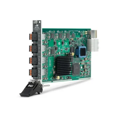
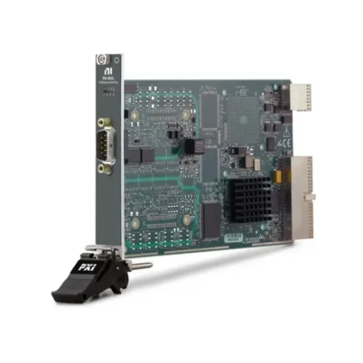
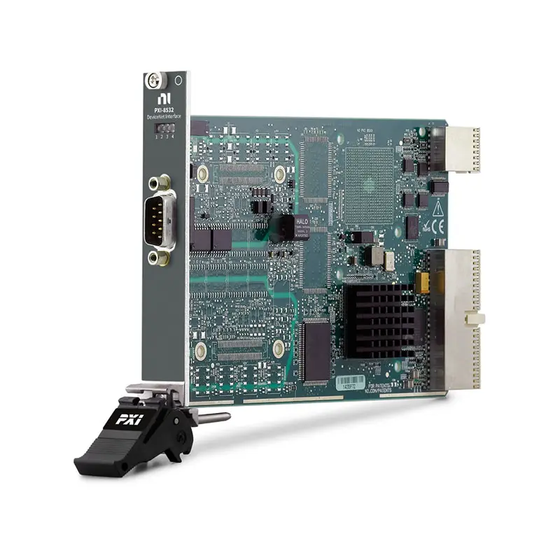
PXI-8532 1-Port PXI DeviceNet Interface Module
Земля PXI-8532 is a one-port PXI DeviceNet interface module designed for industrial communication, automated control and DeviceNet system development. It can be programmed as a high-performance DeviceNet master/scanner or slave using the NI-Industrial Communications for DeviceNet driver.
DeviceNet uses the CAN physical layer while defining additional requirements for network power, connectors, cabling, device addressing and supported communication rates. The PXI-8532 provides an isolated high-speed CAN interface, a male 9-pin D-Sub connector and support for the standard DeviceNet baud rates of 125, 250 and 500 kbit/s.
Key Features of the PXI-8532
- One DeviceNet communication port
- DeviceNet master/scanner functionality
- DeviceNet slave functionality
- 125 kbit/s DeviceNet communication
- 250 kbit/s DeviceNet communication
- 500 kbit/s DeviceNet communication
- CAN-based industrial network interface
- NXP PCA82C251 high-speed CAN transceiver
- Optically isolated physical interface
- 500 Vrms dielectric withstand isolation
- 60 VDC continuous isolation rating
- 9-pin male D-Sub front-panel connector
- Support for as many as 64 compliant DeviceNet nodes
- Explicit messaging support
- Polled and cyclic I/O communication
- PXI hybrid-bus interface
- NI-Industrial Communications for DeviceNet support
- Suitable for industrial automation and embedded control
PXI-8532 Technical Specifications
| Product Model | PXI-8532 |
|---|---|
| Part Number | 781063-01 |
| Product Type | PXI DeviceNet interface module |
| Number of Ports | 1 |
| Supported Network | DeviceNet |
| Physical Layer | High-speed CAN |
| CAN Transceiver | NXP PCA82C251 |
| Hardware Maximum CAN Baud Rate | 1 Mbit/s |
| Supported DeviceNet Baud Rates | 125, 250 and 500 kbit/s |
| Network Roles | Master/scanner or slave |
| Maximum Number of DeviceNet Nodes | 64 compliant devices per network |
| CAN Bus-Line Range | −36 to +36 VDC |
| I/O Connector | 9-pin male D-Sub |
| Network Cable Impedance | 120 Ω nominal |
| Network Termination | 120 Ω resistor at each end of the trunk |
| DeviceNet Network-Power Requirement | 10 to 30 VDC |
| Typical Network-Power Current | 40 mA |
| Maximum Network-Power Current | 100 mA |
| Port-to-Ground Withstand Isolation | 500 Vrms for 5 seconds |
| Port-to-Ground Continuous Isolation | 60 VDC, Measurement Category I |
| PXI Power Requirement at +5 V | 640 mA typical |
| PXI Power Requirement at +3.3 V | 940 mA typical |
| Шинный интерфейс | PXI hybrid |
| Module Format | 3U, one-slot PXI module |
| Dimensions | 10.0 × 16.0 cm |
| Operating Temperature | 0°C to 55°C |
| Operating Shock | 30 g peak, half-sine, 11 ms pulse |
| Operating Random Vibration | 5 to 500 Hz, 0.3 grms |
| Nonoperating Random Vibration | 5 to 500 Hz, 2.4 grms |
| Software Driver | NI-Industrial Communications for DeviceNet |
| Product Lifecycle | Mature; primarily suited to existing DeviceNet systems |
PXI-8532 DeviceNet Baud Rates and Cable Lengths
| Baud Rate | Maximum Trunk Length | Maximum Individual Drop | Maximum Cumulative Drop |
|---|---|---|---|
| 125 kbit/s | 500 m | 6 m | 156 m |
| 250 kbit/s | 250 m | 6 m | 78 m |
| 500 kbit/s | 100 m | 6 m | 39 m |
Maximum cable lengths depend on the cable meeting DeviceNet electrical specifications. The complete installation must also comply with DeviceNet requirements for topology, terminations, network power and drop connections.
PXI-8532 Part Number and Accessories
| Item | Part Number | Описание |
|---|---|---|
| PXI-8532 | 781063-01 | One-port PXI DeviceNet interface module |
| CAN/DeviceNet Terminal Block | 780041-01 | Terminal accessory for CAN, CANopen and DeviceNet wiring |
| DB9F-to-DB9F CAN Cable | 192017-02 | 2 m high-speed CAN cable with single termination |
| DB9F-to-DB9F CAN Cable | 193128-01 | 1 m cable for supported high-speed, FD and low-speed CAN interfaces |
| DB9F-to-DB9F CAN Cable | 193128-02 | 2 m cable for supported high-speed, FD and low-speed CAN interfaces |
| DeviceNet Cable | Application dependent | 120 Ω cable meeting the applicable DeviceNet specification |
Generic CAN cables may not provide the separate network-power conductors and construction required by a complete DeviceNet installation. Verify cable pinout, impedance, shielding, power rating and termination before connecting the PXI-8532.
DeviceNet Interface Architecture
The PXI-8532 connects a PXI controller to an industrial DeviceNet network. It combines a high-speed CAN physical layer with onboard processing and DeviceNet-specific software functions.
Unlike a basic CAN interface, the module supports DeviceNet communication objects, device addressing, explicit messages and I/O connections through a dedicated high-level driver.
DeviceNet Master and Scanner Operation
When configured as a DeviceNet master or scanner, the PXI-8532 manages communication with slave devices on the network. It can establish I/O connections, exchange process data and send explicit configuration messages.
This mode is suitable for controlling industrial devices such as motor drives, valve manifolds, sensors, remote I/O stations and robot controllers from a PXI automation system.
DeviceNet Slave Operation
The PXI-8532 can also operate as a DeviceNet slave. In this configuration, the PXI application represents a DeviceNet device that exchanges data with an external PLC, scanner or industrial controller.
Slave mode is useful for controller testing, equipment simulation and validation of master devices without requiring every physical production component.
Master/Scanner vs Slave Mode
| Operating Mode | PXI-8532 Function | Typical Application |
|---|---|---|
| Master/Scanner | Controls and exchanges data with DeviceNet slave devices | PC-based control, production automation and device configuration |
| Slave | Behaves as a DeviceNet device controlled by an external scanner | PLC validation, controller testing and device simulation |
DeviceNet Baud-Rate Support
The NI-Industrial Communications for DeviceNet driver supports the three standard DeviceNet rates: 125 kbit/s, 250 kbit/s and 500 kbit/s.
Every device on one DeviceNet network must use the same communication rate. A node configured for a different rate will not communicate correctly and may generate bus errors.
Hardware CAN Capability
The PXI-8532 uses an NXP PCA82C251 high-speed CAN transceiver with a hardware range from 10 kbit/s to 1 Mbit/s. However, DeviceNet applications using the NI driver are limited to the standard 125, 250 and 500 kbit/s rates.
The 1 Mbit/s hardware value should not be interpreted as a supported DeviceNet network rate.
CAN-Based Physical Layer
DeviceNet uses the CAN_H and CAN_L differential signal lines for communication. Differential signaling provides strong noise immunity for industrial installations when the correct cable, grounding and termination practices are followed.
The PXI-8532 bus lines tolerate a common-mode range from −36 to +36 VDC within the published hardware specification.
Galvanic Isolation
The DeviceNet port is isolated from the PXI system to help protect the computer and test equipment from ground-potential differences and electrical transients on the industrial network.
The interface provides 500 Vrms dielectric withstand isolation verified by a five-second test and a 60 VDC continuous isolation rating for Measurement Category I circuits.
Isolation reduces the risk of damage but does not replace correct grounding, surge protection and DeviceNet installation practices.
DeviceNet Network Power
A DeviceNet cable carries communication signals and network power. The network power supply is separate from the PXI chassis power that operates the module.
The DeviceNet interface requires network power within the specified range for correct operation. Verify polarity before connection because reversed or excessive voltage can damage network equipment.
External Network-Power Supply
The DeviceNet network normally requires a regulated DC power supply connected to the V+ and V− conductors. The power supply must support the total current required by all connected nodes, cables and accessories.
Locate and ground the power supply according to the applicable DeviceNet design rules. Consider cable voltage drop when devices are installed far from the power source.
9-Pin D-Sub Connector
The PXI-8532 uses one male 9-pin D-Sub connector for DeviceNet signals. The connection provides CAN_H, CAN_L, network power, common and shield-related contacts.
Confirm the pinout before connecting third-party cables. A cable intended for another CAN interface may use the same connector while assigning network power or shield signals differently.
DeviceNet Connector Signals
| Signal | Function |
|---|---|
| CAN_H | High side of the differential CAN communication pair |
| CAN_L | Low side of the differential CAN communication pair |
| V+ | Positive DeviceNet network-power connection |
| V− | DeviceNet network-power return |
| COM | Communication common connection where applicable |
| SHLD | Cable shield connection |
DeviceNet Cable Requirements
Use cable specifically rated for DeviceNet networks. The cable should provide a nominal communication-pair impedance of 120 Ω and conductors suitable for network power.
Belden 3084A is an example of a cable identified in legacy NI documentation as meeting DeviceNet requirements for many applications. Verify suitability for the required environment, cable length and current.
Network Termination
The DeviceNet trunk must be terminated with a 120 Ω resistor at each physical end. The resistors should be installed across CAN_H and CAN_L and rated to dissipate at least 0.25 W.
Do not install a termination resistor at every node. Excessive termination lowers the bus impedance and can prevent communication.
DeviceNet Network Topology
DeviceNet commonly uses a trunkline-dropline architecture. The main trunk connects the two end terminators, while shorter drop cables connect individual devices to the trunk.
Maximum trunk and cumulative drop lengths decrease as the baud rate increases. The network should not be wired as an uncontrolled star unless the selected components and DeviceNet design rules specifically support that arrangement.
Support for Multiple DeviceNet Nodes
A properly designed DeviceNet network can contain as many as 64 nodes, including the scanner. Each node must have a unique MAC ID.
Actual network capacity depends on device compliance, cable length, power availability, communication traffic and the scanner configuration.
Explicit Messaging
Explicit messaging is used for configuration, diagnostics and access to DeviceNet object attributes. The PXI-8532 software interface allows applications to send and receive these request-and-response messages.
Typical uses include reading device identity, changing configuration values, retrieving diagnostic status and accessing vendor-specific parameters.
I/O Messaging
DeviceNet I/O connections exchange process data between a scanner and network devices. Depending on the device and software configuration, communication may use polled, cyclic or change-of-state behavior.
I/O messaging is suitable for repeatedly transferring control commands, status words and sensor values with lower overhead than individual explicit messages.
Industrial Motor and Drive Control
The PXI-8532 can act as a scanner for DeviceNet motor drives, starters and motion-related equipment. Test software can write commands, read operating status and verify diagnostic responses.
Safety-related motion and machine-protection functions should remain implemented through appropriately rated independent hardware rather than relying solely on a general-purpose test application.
Remote I/O and Sensor Testing
DeviceNet remote I/O stations and sensors can be connected to the PXI-8532 for automated configuration and data verification. The PXI system can stimulate field signals, collect DeviceNet values and compare the results.
This supports production testing, maintenance diagnostics and validation of industrial control components.
Robot Controller Communication
The PXI-8532 can communicate with robot controllers that provide a compatible DeviceNet slave or master interface. The PXI system can exchange command and status data as part of an automated test or control application.
Confirm the robot-controller role, DeviceNet baud rate, node address and required I/O assembly before configuring the communication session.
PC-Based and Embedded Control
The module allows a PXI controller to operate as part of a DeviceNet control system. Applications can combine industrial communication with measurement, data acquisition, motion control and test sequencing.
This integration is useful for laboratory automation, embedded control prototypes and production systems that require synchronized measurements alongside DeviceNet data.
Human-Machine Interface Applications
A PXI application can use the PXI-8532 to read DeviceNet process variables and display them in a custom operator interface. Authorized users can also send configuration or control commands to network devices.
Access permissions, error handling and safe-state behavior should be included when the interface can change machine operation.
Network Management and Diagnostics
The PXI-8532 can support DeviceNet network-management utilities that identify nodes, read device information, monitor communication and retrieve diagnostic status.
Diagnostic applications can help locate duplicate node addresses, mismatched baud rates, missing devices, wiring faults and network-power problems.
NI-Industrial Communications for DeviceNet
The required driver is NI-Industrial Communications for DeviceNet. It provides a high-level application programming interface for scanner, slave, explicit-message and I/O communication.
The software includes LabVIEW support and example programs for common DeviceNet operations. Confirm operating-system, LabVIEW and driver-version compatibility before installing the PXI-8532 in an existing system.
NI-DNET Compatibility and Migration
Legacy DeviceNet systems may use the older NI-DNET driver and PXI-8461/D hardware. The PXI-8532 uses NI-Industrial Communications for DeviceNet rather than NI-XNET.
Later DeviceNet driver releases provide compatibility VIs for migrating certain NI-DNET applications. Existing programs should still be tested carefully because driver architecture, initialization and explicit-message handling may differ.
NI-XNET vs DeviceNet Driver
NI-XNET is primarily used for supported CAN, LIN, FlexRay and Automotive Ethernet interfaces. The PXI-8532 requires NI-Industrial Communications for DeviceNet for its DeviceNet master and slave functionality.
Installing NI-XNET alone does not provide the required DeviceNet programming support for the PXI-8532.
PXI Hybrid Chassis Integration
The PXI-8532 uses a PXI hybrid bus connection and occupies one 3U chassis slot. It can be combined with analog input, digital I/O, motion, switching and other industrial communication modules.
Before installation, verify chassis slot compatibility, PXI controller support, available cooling and the required software versions.
Typical PXI-8532 Applications
- DeviceNet master and scanner control
- DeviceNet slave emulation
- Industrial automation development
- PLC and scanner validation
- Motor-drive communication testing
- Robot-controller integration
- Valve-manifold testing
- Remote I/O validation
- Industrial sensor testing
- DeviceNet device configuration
- Explicit-message diagnostics
- PC-based control systems
- Embedded control development
- Human-machine interface systems
- Production end-of-line testing
Production Test Systems
The PXI-8532 can configure and communicate with DeviceNet products during production testing. A test sequence can verify device identity, communication status, input and output data, diagnostic functions and configuration parameters.
Combining DeviceNet communication with PXI measurement modules allows electrical signals and network data to be validated in one automated station.
PXI-8532 Troubleshooting
The PXI-8532 is not detected in NI MAX
Confirm that the module is fully installed in a compatible PXI or hybrid slot. Check chassis power, controller communication and installation of the required NI DeviceNet driver.
The DeviceNet network remains offline
Verify network power, polarity, CAN_H and CAN_L wiring, cable continuity and the presence of exactly two 120 Ω termination resistors. Confirm that all devices use the same baud rate.
The PXI-8532 cannot detect a slave device
Check the slave’s MAC ID, baud rate and network power. Verify that another device is not using the same MAC ID and confirm that the scanner configuration includes the required device.
The network reports frequent CAN errors
Inspect cable impedance, trunk and drop lengths, shield connections and termination. Look for loose connectors, excessive untwisted wiring, electrical noise or incorrect grounding.
The driver does not offer the required DeviceNet functions
Confirm that NI-Industrial Communications for DeviceNet is installed. NI-XNET alone does not provide PXI-8532 DeviceNet master/scanner and slave functions.
A migrated NI-DNET application reports errors
Review the NI-DNET migration documentation and replace or reconfigure incompatible initialization and messaging functions. Confirm that the application uses driver VIs intended for the installed DeviceNet driver version.
Explicit messaging fails
Verify the device class, instance, attribute and service parameters. Confirm that the target device supports the requested object and that an existing I/O connection does not restrict the operation.
DeviceNet communication stops under load
Check network utilization, scan-list configuration and application-loop timing. Reduce unnecessary explicit messages and verify that cyclic or polled I/O intervals are appropriate for the selected baud rate.
The module works as a scanner but not as a slave
Confirm that the installed DeviceNet driver version supports PXI-8532 slave operation and that the interface MAC ID, I/O assemblies and connection parameters are configured correctly.
PXI-8532 Comparison with Similar Interfaces
| Модель | Interface | Form Factor | Best Suited For |
|---|---|---|---|
| PXI-8532 | One-port DeviceNet | PXI hybrid | DeviceNet integration inside a modular PXI system |
| PCI-8532 | One-port DeviceNet | Desktop PCI | DeviceNet communication from an industrial or desktop PC |
| PXI-8461/D | Legacy DeviceNet | PXI | Maintaining systems developed around the legacy NI-DNET driver |
| PXI-8512 | High-speed CAN and CAN FD | PXI | Raw CAN applications that do not require DeviceNet services |
| PXI-8531 | Industrial Ethernet and EtherCAT master interface | PXI | EtherCAT industrial control rather than DeviceNet |
PXI-8532 vs PCI-8532
The PXI-8532 and PCI-8532 provide similar one-port DeviceNet communication capabilities. The main difference is the computer interface and mechanical format.
Choose the PXI-8532 for a modular PXI test or automation system. Choose the PCI-8532 when the interface must be installed in a compatible desktop or industrial PC with a conventional PCI slot.
PXI-8532 vs PXI-8461/D
The PXI-8461/D is a legacy DeviceNet interface commonly associated with the older NI-DNET driver. The PXI-8532 uses the newer NI-Industrial Communications for DeviceNet software architecture.
Choose hardware based on the existing application, driver version and operating-system compatibility. Migrating a mature NI-DNET system may require software changes even when the overall DeviceNet function remains similar.
PXI-8532 vs PXI-8512
Although both modules use a CAN-based physical layer, the PXI-8532 is designed specifically for DeviceNet. It provides higher-level scanner, slave and explicit-message functions through the DeviceNet driver.
The PXI-8512 is intended for CAN and CAN FD applications using NI-XNET. It should not be treated as a direct replacement when the application requires DeviceNet protocol services.
Recommended Related Products
- PCI-8532 1-Port DeviceNet Interface Device
- PXI-8461/D Legacy DeviceNet Interface Module
- PXI-8512 High-Speed CAN Interface Module
- PXI-8513 Software-Selectable CAN Interface Module
- PXIe-8510 Vehicle Multiprotocol Interface Module
- PXI-8531 Industrial Ethernet Interface Module
- View More NI PXI and PXI Express Modules
Selecting the Right Industrial Network Interface
Choose the PXI-8532 when the application requires DeviceNet master/scanner or slave functionality in a PXI system. It is especially relevant for maintaining or expanding established DeviceNet automation and test platforms.
Select a CAN interface such as the PXI-8512 when the application uses raw CAN or CAN FD rather than DeviceNet. Use an EtherCAT interface when the industrial network is based on EtherCAT instead of CAN-based DeviceNet.
Because NI classifies the PXI-8532 as a mature product that is not recommended for new designs, confirm long-term hardware availability, driver support and lifecycle requirements before selecting it for a new platform.
Why Choose the PXI-8532?
- Adds DeviceNet communication to a PXI system
- Operates as a DeviceNet master/scanner or slave
- Supports all three standard DeviceNet baud rates
- Provides an isolated high-speed CAN physical layer
- Supports explicit and I/O messaging
- Communicates with as many as 64 compliant network nodes
- Integrates industrial communication with PXI measurements
- Supports PC-based control and production testing
- Works with NI-Industrial Communications for DeviceNet
- Supports maintenance of established DeviceNet systems
Frequently Asked Questions
What is the PXI-8532?
The PXI-8532 is a one-port PXI DeviceNet interface module for industrial communication, master/scanner control and slave-device emulation.
What is the PXI-8532 part number?
The standard NI part number for the PXI-8532 is 781063-01.
Which DeviceNet baud rates are supported?
The NI DeviceNet driver supports 125, 250 and 500 kbit/s communication with the PXI-8532.
Why does the specification list a 1 Mbit/s maximum rate?
The high-speed CAN transceiver has a hardware capability of up to 1 Mbit/s. DeviceNet software operation is limited to the standard DeviceNet rates of 125, 250 and 500 kbit/s.
Can the PXI-8532 operate as a DeviceNet master?
Yes. It can operate as a DeviceNet master or scanner and manage communication with slave devices.
Can it operate as a DeviceNet slave?
Yes. With a compatible driver version, the PXI-8532 can emulate a DeviceNet slave controlled by an external scanner.
Which driver is required?
The PXI-8532 requires NI-Industrial Communications for DeviceNet. NI-XNET alone does not provide its DeviceNet protocol functions.
What connector does the PXI-8532 use?
The module uses one male 9-pin D-Sub connector for CAN signals, DeviceNet network power, common and shield connections.
Does the DeviceNet network require external power?
Yes. DeviceNet carries network power separately from the PXI chassis power. Verify the required voltage, current capacity and polarity before connection.
How should a DeviceNet network be terminated?
Install one 120 Ω resistor across CAN_H and CAN_L at each physical end of the trunk. Do not terminate every node.
How many nodes can be connected?
A compliant DeviceNet network can support as many as 64 nodes, including the scanner. Actual capacity depends on power, wiring and traffic requirements.
Is the PXI-8532 recommended for new systems?
NI classifies the PXI-8532 as a mature product and does not recommend it for new designs. It remains useful for maintaining and expanding compatible existing DeviceNet systems.
Request a Quote for the PXI-8532
Contact us for current availability, lead time and project pricing for the PXI-8532 1-Port PXI DeviceNet Interface Module. We can also help identify compatible DeviceNet terminal blocks, cables, PXI chassis and related NI industrial communication modules for your control or automated test system.















