






Quick Answer: PXI system architecture combines a rugged modular chassis, a PCI- or PCI Express-based backplane, a system controller, instrument modules, shared timing and trigger resources, drivers, and test software. The controller communicates with the modules through the chassis backplane, while dedicated clocks and trigger lines coordinate measurements across instruments. This layered design allows engineers to build compact, synchronized, software-defined automated test systems.
What Is PXI System Architecture?
PXI system architecture describes how the physical chassis, controller, backplane, instrument modules, timing resources, drivers, and application software work together as one test and measurement platform. PXI stands for PCI eXtensions for Instrumentation. It adapts commercial computer bus technology for measurement systems and adds the mechanical, electrical, timing, synchronization, cooling, and software features required by professional instrumentation.
A PXI system is not simply a group of plug-in cards. It is a coordinated architecture in which each layer has a specific responsibility. The chassis supplies power, cooling, data paths, clocks, and triggers. The controller runs the operating system and test program. Instrument modules acquire or generate signals. Drivers expose the hardware to software, and the application coordinates the complete test sequence.
This organization is what makes PXI suitable for automated test equipment, data acquisition, RF validation, semiconductor testing, automotive electronics, aerospace systems, and production-line testing. Multiple instruments can share a common platform and operate with deterministic timing relationships that would be more difficult to achieve with separately connected benchtop instruments.
1Physical LayerThe chassis provides the enclosure, slots, power rails, cooling, mechanical alignment, and electromagnetic environment.
2Data-Bus LayerPCI in PXI or PCI Express in PXIe moves commands and measurement data between the controller and modules.
3Timing LayerReference clocks, trigger buses, star lines, and differential signals coordinate instruments across the backplane.
4Software LayerDrivers, APIs, test executives, and user applications configure hardware, execute tests, process data, and report results.
The Five Layers of a PXI System
1. Chassis, Power, and Cooling Layer
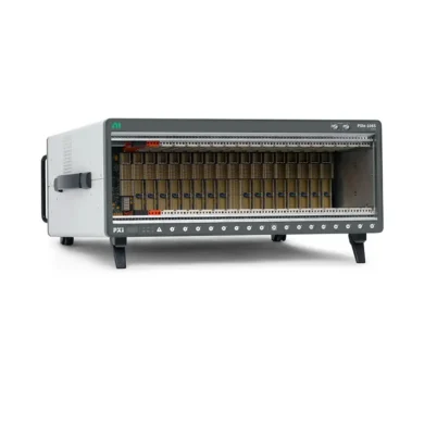
Земля PXI or PXIe chassis is the structural and electrical foundation of the system. It holds the system controller and peripheral modules in defined slots and connects them to a common backplane. The chassis also distributes power, removes heat, identifies slot capabilities, and provides timing and trigger resources.
PXI systems commonly use the compact 3U Eurocard form factor, although 6U implementations also exist. Chassis sizes range from compact systems with only a few slots to large platforms designed for high-channel-count or multi-instrument applications. The number of physical slots does not by itself define system capacity: one slot is normally reserved for the controller, and a module may occupy more than one slot because of its width, power, cooling, or connector requirements.
Power and cooling are architectural considerations rather than secondary accessories. High-speed digitizers, RF instruments, FPGA modules, and powerful embedded controllers can produce significant heat. A chassis must provide adequate power on the required voltage rails and sufficient airflow for every installed module. If thermal capacity is inadequate, modules may reduce performance, report errors, or operate outside their specified accuracy.
Design reminder: Select a chassis by usable slots, slot types, backplane topology, per-slot bandwidth, total system bandwidth, power, cooling, timing features, and acoustic or environmental requirements—not only by the advertised slot count.
2. Backplane and Data-Transport Layer
The backplane is the internal communication fabric of a PXI system. It carries data between the controller and the instrument modules and also distributes timing, triggering, and identification signals. Traditional PXI uses the parallel PCI bus, while PXI Express, commonly called PXIe, incorporates serial PCI Express links.
In a traditional PCI-based PXI system, several devices may share a bus segment. A bridge can connect additional segments when more slots are required. This architecture provides low-latency access and remains effective for instruments that do not continuously transfer large datasets, including many digital multimeters, switching modules, industrial interfaces, and general-purpose I/O devices.
PXIe uses a switched, point-to-point architecture. PCI Express lanes connect the controller to PCIe switches in the chassis and then to peripheral slots. A link may contain one or more lanes, commonly expressed as x1, x4, x8, or x16. Link width and PCIe generation influence the theoretical transport capacity, but the realized throughput also depends on the controller interface, switch topology, module design, driver, transfer size, and simultaneous traffic from other devices.
This switched architecture is particularly valuable for instruments that stream large volumes of data, such as high-speed oscilloscopes, digitizers, wideband RF analyzers, vector signal transceivers, high-speed digital instruments, and FPGA-based processing modules.
| Architecture Element | Traditional PXI | PXI Express | Practical Effect |
|---|---|---|---|
| Computer bus | Parallel PCI | Serial PCI Express | PXIe supports much higher scalable data throughput. |
| Connection model | Devices may share PCI bus segments | Switched point-to-point PCIe links | PXIe can allocate bandwidth by slot and route traffic through switches. |
| Reference timing | 10 MHz reference clock | 10 MHz plus 100 MHz differential reference resources | PXIe supports higher-performance synchronization architectures. |
| Trigger resources | PXI trigger bus and PXI star trigger | Legacy resources plus differential star triggers | PXIe provides additional high-quality clock and trigger paths. |
| Best fit | Moderate-bandwidth measurement, switching, control, and legacy systems | High-speed streaming, RF, digitizers, FPGA, and modern mixed-instrument systems | The required instruments and data rates should determine the platform. |
3. Controller and Processing Layer
Земля PXI controller is the computing node that enumerates the installed hardware, loads device drivers, runs the test application, transfers data, performs analysis, and communicates with external systems. It may be an embedded controller installed in the chassis or an external computer connected through a remote-control interface.
An embedded controller occupies the system slot and integrates the processor, memory, storage, network ports, USB interfaces, and display connections into the chassis. This produces a compact stand-alone system with fewer external cables. It is often selected for production test racks, deployed systems, real-time test platforms, and applications where the chassis must operate as a self-contained instrument.
A remote-control architecture uses a desktop PC, workstation, server, or industrial computer connected to the chassis through a supported PCI Express, MXI, or Thunderbolt-based interface. The interface module installed in the system slot extends the host computer's PCI Express hierarchy into the PXI chassis. To the operating system and drivers, the PXI modules can appear as locally connected PCI or PCIe devices.
Remote control can provide greater flexibility in processor, GPU, memory, and storage selection. It can also separate the operator computer from a noisy test rack or make future computer upgrades easier. However, the remote interface and its link width may become a throughput boundary. The controller-to-chassis connection must therefore be included in the complete data-bandwidth calculation.
Architecture decision: Choose an embedded controller for an integrated, compact, and maintainable platform. Consider remote control when the system needs workstation-class processing, specialized computing hardware, independent PC upgrades, or physical separation between the operator and the test chassis.
4. Instrument and I/O Layer
PXI and PXIe modules provide the actual measurement, signal-generation, switching, communication, and control functions. Each module contains specialized analog, digital, RF, or FPGA hardware, but it uses the shared chassis architecture for power, data transport, and synchronization.
Typical module categories include:
- Oscilloscopes and digitizers
- Digital multimeters
- Arbitrary waveform and function generators
- RF signal generators and analyzers
- Vector signal transceivers
- Source measure units and programmable power supplies
- Switching and relay modules
- Data acquisition modules
- Digital pattern and high-speed digital I/O modules
- CAN, LIN, FlexRay, serial, Ethernet, and other communication interfaces
- FPGA, FlexRIO, and reconfigurable I/O modules
- Timing and synchronization modules
Modularity separates instrument selection from the rest of the platform. Engineers can replace an instrument, increase channel count, or add a new function without rebuilding the entire system. However, every module must be checked for electrical range, accuracy, bandwidth, connector type, required accessories, driver support, slot type, bus interface, power, cooling, and operating-system compatibility.
5. Driver, API, and Application Layer
PXI is a software-defined architecture. Hardware creates the measurement capability, but software determines what the system does. A complete software stack normally includes firmware, a device driver, a programming API, configuration utilities, test-development software, analysis code, data storage, and reporting tools.
Drivers translate application commands into hardware operations and expose functions such as channel configuration, triggering, acquisition, generation, calibration, routing, and error reporting. Standard interfaces such as VISA can help applications communicate with instruments from different vendors, while instrument-specific drivers expose advanced features.
Applications may be developed in LabVIEW, TestStand, C/C++, C#, Python, MATLAB, or another supported environment. In an automated system, the software layer typically performs the following sequence:
- Discover and initialize the chassis and modules.
- Load configuration and calibration information.
- Configure ranges, sample rates, clocks, triggers, and signal routes.
- Execute stimulus and measurement operations.
- Transfer data into controller memory or directly to storage.
- Analyze measurements and compare them with test limits.
- Record results, generate reports, and update manufacturing or laboratory databases.
- Release resources and place the hardware in a safe state.
How PXI Slots Are Organized
A PXI or PXIe chassis can include several slot types. Their front-panel glyphs and connector layouts identify the type of module that each slot is designed to accept. Understanding the slot architecture is essential when planning a system or reusing legacy modules.
System Controller Slot
The system slot is normally the leftmost slot, designated Slot 1. It accepts an embedded controller or a remote-control interface module. The system controller connects to the backplane bus and provides the root of the PCI or PCI Express device hierarchy.
Peripheral Slots
Peripheral slots hold instrument and I/O modules. A PXI peripheral slot is designed for PCI-based PXI modules. A PXIe peripheral slot is designed for PCI Express-based modules. Available PCIe lane width and the way those lanes connect through the backplane switches can vary by slot and chassis model.
Hybrid Peripheral Slots
A PXIe hybrid slot is designed to support a broader mixture of compatible module types. It can accept PXIe modules and hybrid-slot-compatible PXI modules. However, not every older PXI module can be installed in a hybrid slot because the legacy connector configuration may differ. Mechanical fit, connector type, electrical bus support, driver support, and operating-system support must all be verified.
System Timing Slot
The system timing slot provides access to dedicated star-trigger and differential timing resources. A timing and synchronization module installed here can distribute or receive clocks and triggers with controlled path relationships to peripheral slots. If advanced timing is not required, some chassis permit the system timing slot to accept a compatible peripheral module.
| Slot Type | Typical Hardware | Architectural Role | Compatibility Check |
|---|---|---|---|
| System slot | Embedded controller or remote-control module | Hosts or connects the system controller | Controller interface, chassis generation, bandwidth, OS, and driver support |
| PXI peripheral slot | PCI-based PXI module | Provides a legacy parallel PCI connection | PXI connector, voltage keying, power, driver, and chassis support |
| PXIe peripheral slot | PXIe module | Provides PCI Express connectivity | Lane width, PCIe generation, power, cooling, and software support |
| Hybrid slot | PXIe or hybrid-compatible PXI module | Supports mixed-platform configurations | Do not assume all legacy PXI modules are hybrid-compatible |
| System timing slot | Timing/synchronization module or supported peripheral | Accesses star and differential timing paths | Chassis routing, module function, and target synchronization method |
PXI Timing and Trigger Architecture
Integrated timing and triggering distinguish PXI from a simple collection of computer expansion cards. The backplane gives modules access to shared reference clocks and dedicated trigger paths, allowing multiple instruments to begin operations, sample signals, or generate outputs with known timing relationships.
10 MHz System Reference Clock
PXI provides a 10 MHz system reference clock, commonly identified as PXI_CLK10, to peripheral slots. Modules can use this signal as a frequency reference or as a basis for phase-locking their internal timebases. Sharing a reference helps prevent the independent oscillators in different instruments from drifting apart during long acquisitions or generations.
100 MHz Differential Reference Clock
PXIe adds a 100 MHz differential system reference clock, commonly called PXIe_CLK100, along with a synchronization signal that defines its phase relationship to the 10 MHz clock. Differential signaling supports higher-frequency clock distribution with improved signal integrity. The exact use of these resources depends on the chassis and module design.
PXI Триггерная шина
The PXI trigger bus contains shared trigger lines routed across the backplane. Modules can use these lines to start acquisitions, coordinate stimulus and response, signal events, or create handshaking relationships. Because the lines are available internally, synchronization may require fewer external cables.
Star and Differential Star Triggers
Star trigger architecture uses individual point-to-point connections between a central timing slot and peripheral slots. Compared with a shared bus, this arrangement can provide more closely matched signal paths. PXIe expands the concept with differential star-trigger resources that support higher-quality, higher-frequency clock and trigger distribution.
Local Bus
PXI also defines local-bus connections between adjacent slots. Compatible modules can use these paths for application-specific signal transfer without routing through the system controller. Actual local-bus use is module-dependent and must be confirmed in the instrument and chassis documentation.
Synchronization principle: Sharing a trigger aligns an event, while sharing or disciplining a reference clock controls long-term frequency and phase relationships. High-quality synchronized systems often require both a common timebase and a defined trigger route.
How Data Moves Through a PXI System
Understanding data flow helps engineers size the controller, bus, memory, and storage correctly. Consider a PXIe digitizer acquiring a high-speed waveform:
- The test application sends configuration commands through the driver to the digitizer.
- The module configures its analog front end, sample clock, onboard memory, and trigger engine.
- A backplane or front-panel trigger starts the acquisition.
- The analog-to-digital converter samples the signal and writes data into onboard memory.
- Direct memory access transfers blocks of data through the PCIe link and chassis switch fabric into controller memory.
- The application processes, displays, or streams the data to storage.
- Results are compared with limits and passed to a database, report, or higher-level automation system.
The slowest stage in this path can limit sustainable throughput. A module may have an extremely high sampling rate but only capture short records in onboard memory. Continuous streaming requires the module bus interface, chassis topology, controller link, system memory, processor, and storage device to sustain the required rate together.
Multiple high-bandwidth modules can also share switch uplinks. Adding their individual maximum bandwidth figures does not guarantee that all modules can stream simultaneously at those rates. A system bandwidth diagram from the chassis documentation is therefore essential for data-intensive designs.
Bandwidth planning: Calculate the payload data rate for every continuously streaming module, include channel count and sample width, allow protocol and software overhead, then compare simultaneous traffic with per-slot, switch-segment, controller-link, memory, and storage limits.
PXI System Topology Examples
Basic Automated Measurement System
A general automated test system may use an eight-slot PXIe chassis, an embedded controller, a digital multimeter, an oscilloscope, a waveform generator, digital I/O, and a relay matrix. The controller configures the instruments, switching connects each test point, and shared triggers coordinate stimulus and measurement. Test software executes the sequence and records pass/fail results.
High-Speed RF Validation System
An RF architecture may combine a high-bandwidth PXIe chassis, a powerful controller, a vector signal transceiver, RF switching, a digitizer, FPGA processing, and a system timing module. PCIe links move wideband IQ data, while reference clocks and differential trigger paths coordinate generation and analysis. The topology must be chosen to avoid placing several high-data-rate modules behind an insufficient shared switch link.
High-Channel-Count Data Acquisition System
A data acquisition platform may contain multiple analog input modules, sensor signal conditioning, digital I/O, and synchronization hardware. Shared clocks align channels across modules, and DMA moves acquired data to controller memory. If the system records continuously, storage performance and file-management strategy can be as important as chassis bandwidth.
Multi-Chassis Architecture
When one chassis does not provide enough slots, several chassis can be connected through supported expansion interfaces. A multi-chassis system introduces additional questions: which controller owns each chassis, how data crosses expansion links, how device addresses are managed, and how clocks and triggers are distributed between chassis.
For phase-aligned or time-correlated measurements, an external reference, timing modules, cabling with known propagation characteristics, or time-based synchronization technology may be required. The correct method depends on acceptable skew, distance, environmental conditions, and whether the systems must remain synchronized after triggers have occurred.
PXI Architecture vs. Benchtop Instrument Architecture
A benchtop test system normally connects independent instruments through Ethernet, USB, GPIB, or LAN-based protocols. Each instrument includes its own enclosure, power supply, processor, display, timebase, and communication interface. This arrangement is convenient for manual laboratory work and gives each instrument operational independence.
PXI consolidates these functions. Modules share the chassis, controller, data bus, timing infrastructure, and software environment. The result can offer higher channel density, lower communication latency, more precise synchronization, reduced rack space, and better automation. The tradeoff is that system design requires careful compatibility, thermal, bandwidth, driver, and software planning.
| Design Factor | PXI/PXIe Architecture | Benchtop Architecture |
|---|---|---|
| Integration | Modules share a chassis, controller, backplane, and timing resources | Each instrument is a separate device connected by cables |
| Синхронизация | Dedicated internal clocks and trigger routes | Often uses external trigger and reference cables |
| Automation | Designed for software-controlled multi-instrument systems | Automatable, but communication and coordination may be less integrated |
| Scalability | Add or replace compatible modules within chassis constraints | Add complete instruments, rack space, cables, and interfaces |
| Manual use | Often requires a PC interface and application software | Front panels are convenient for interactive troubleshooting |
| Engineering effort | Requires system-level compatibility and topology design | Individual instruments are often easier to deploy independently |
How to Design a PXI System Architecture
Define Signals and Test Functions
Start with the device under test rather than a preferred chassis model. Document every signal type, range, bandwidth, accuracy, channel count, source requirement, switching path, communication bus, isolation requirement, and safety limit. This produces the functional instrument list.
Calculate Data Rates
For digitizers and acquisition modules, estimate the data rate from sample rate, number of channels, and bytes per sample. Identify which modules will stream simultaneously and which only transfer short records. Include analysis, display, network, and storage requirements.
Define Timing Relationships
Specify which channels must be frequency-locked, phase-aligned, triggered together, or correlated to an external time reference. Define acceptable skew, jitter, drift, and synchronization duration. This determines whether standard trigger lines are sufficient or a system timing module is required.
Select Modules Before Finalizing the Chassis
Identify modules that meet the measurement requirements, then record their bus type, occupied slot width, connector style, power consumption, cooling needs, driver versions, and supported operating systems. The combined module list determines the necessary slot types and chassis capacity.
Review Backplane Topology
Map every high-bandwidth module to a slot and examine how the slot connects to the controller through the chassis switches. Reserve the best-connected slots for the most demanding instruments. Verify that simultaneous traffic does not exceed a shared upstream link.
Size the Controller
Choose processor performance, memory, storage, network ports, operating system, and lifecycle according to the workload. Real-time control, inline signal processing, machine vision, database communication, and large waveform analysis may require significantly different controller configurations.
Leave Capacity for Expansion
Reserve slots, bandwidth, power, cooling, storage, and I/O for expected future functions. Spare physical slots are not useful if they do not have the correct interface or if system power and bandwidth are already fully allocated.
Procurement advice: A complete PXI bill of materials should include the chassis, controller or remote interface, modules, terminal blocks, cables, adapters, switching accessories, storage, software licenses, drivers, calibration requirements, rack hardware, and any timing or synchronization components.
Common PXI Architecture Mistakes
- Assuming physical fit guarantees compatibility: connector, bus, slot, firmware, driver, and operating-system support must also match.
- Selecting a chassis only by slot count: usable slots, bandwidth topology, power, cooling, and timing resources may be more important.
- Ignoring shared switch bandwidth: several fast modules can compete for one upstream PCIe link.
- Using sample rate as the continuous streaming rate: onboard memory and interface throughput may limit sustained acquisition.
- Confusing triggering with clock synchronization: a common start trigger does not prevent independent sample clocks from drifting.
- Forgetting accessory compatibility: terminal blocks, cables, front-end conditioning, and fixtures determine whether a module can connect safely to the application.
- Choosing software after hardware: driver availability, API support, OS compatibility, and lifecycle should be verified before purchase.
- Leaving no thermal margin: high-performance modules need adequate airflow, especially in dense rack installations.
Frequently Asked Questions About PXI Architecture
What are the main components of a PXI system?
A typical system includes a PXI or PXIe chassis, an embedded or remote controller, instrument modules, timing and triggering resources, drivers, and test software. Accessories such as terminal blocks, cables, signal conditioning, switching, and fixtures complete the connection to the device under test.
What is the PXI backplane?
The backplane is the internal circuit assembly that connects the controller and modules. It distributes PCI or PCI Express data paths, power, reference clocks, trigger lines, slot identification signals, and other instrumentation resources defined by the platform.
Why is the controller normally installed in Slot 1?
PXI defines the system slot at the left side of the chassis. An embedded controller or remote interface installed there becomes the root connection for discovering and communicating with the peripheral modules on the backplane.
What is the difference between a system slot and a system timing slot?
The system slot holds the controller or remote-control interface. The system timing slot is designed for a timing and synchronization module that accesses dedicated star and differential timing routes. They serve different architectural functions.
Can PXI and PXIe modules operate in the same chassis?
They can in a chassis with suitable PXI, PXIe, or hybrid slots, but compatibility is module- and slot-specific. Some legacy PXI modules are not hybrid-slot-compatible. Chassis and module documentation must be checked before installation.
Does every PXIe slot have the same bandwidth?
No. Slots may use different PCIe lane widths and may connect through different switch segments. Several slots may also share an upstream link. Review the chassis bandwidth topology rather than assuming identical performance.
How are PXI instruments synchronized?
Depending on the required accuracy, instruments can share backplane reference clocks, trigger-bus lines, star triggers, differential star triggers, front-panel signals, or an external time reference. A timing module may replace or discipline the chassis clock and coordinate multiple chassis.
Can a PXI module transfer data without using the CPU for every word?
Yes. Many instruments use direct memory access to transfer blocks of data between module memory and system memory with limited processor intervention. Actual transfer behavior depends on the module, driver, and acquisition mode.
Is PXIe always necessary for a new system?
PXIe is generally preferred for new high-performance or expandable systems, especially when using RF, digitizer, FPGA, or continuous-streaming modules. Traditional PXI can still be appropriate for existing systems and moderate-bandwidth instruments where its performance and lifecycle meet the application.
What information is needed before configuring a PXI architecture?
Important inputs include signal types, ranges, bandwidth, accuracy, channel count, sample rate, continuous data rate, synchronization tolerance, required software, operating system, environmental conditions, available rack space, budget, delivery schedule, and future expansion plans.
Заключение
PXI system architecture integrates computer bus technology with the physical, timing, synchronization, power, cooling, and software features required for modular instrumentation. Its layered design connects a controller to specialized instrument modules through a common chassis backplane while shared clocks and triggers coordinate their operation.
Traditional PXI uses PCI, while PXIe uses a switched PCI Express fabric and adds advanced differential timing resources. The correct architecture depends on instrument functions, data throughput, timing precision, slot compatibility, software support, environmental requirements, and expected expansion.
A well-designed system is more than a compatible list of model numbers. The chassis topology, controller link, module interfaces, timing plan, data path, thermal capacity, drivers, and application software must work as a complete system. When these elements are planned together, PXI can provide a compact, repeatable, synchronized, and scalable platform for modern automated testing.
Categories
Latest Articles
Products on Sale


Need Help Choosing a Product?
Contact our sales team for product selection, pricing, availability and lead-time information.
sales@pxisource.com