






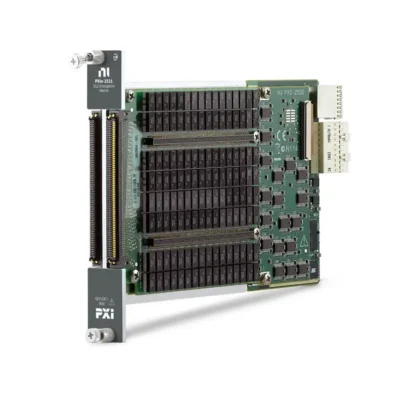
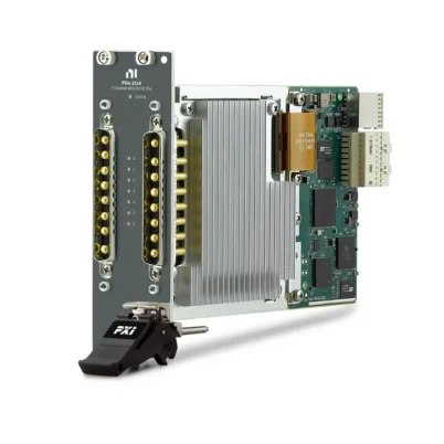
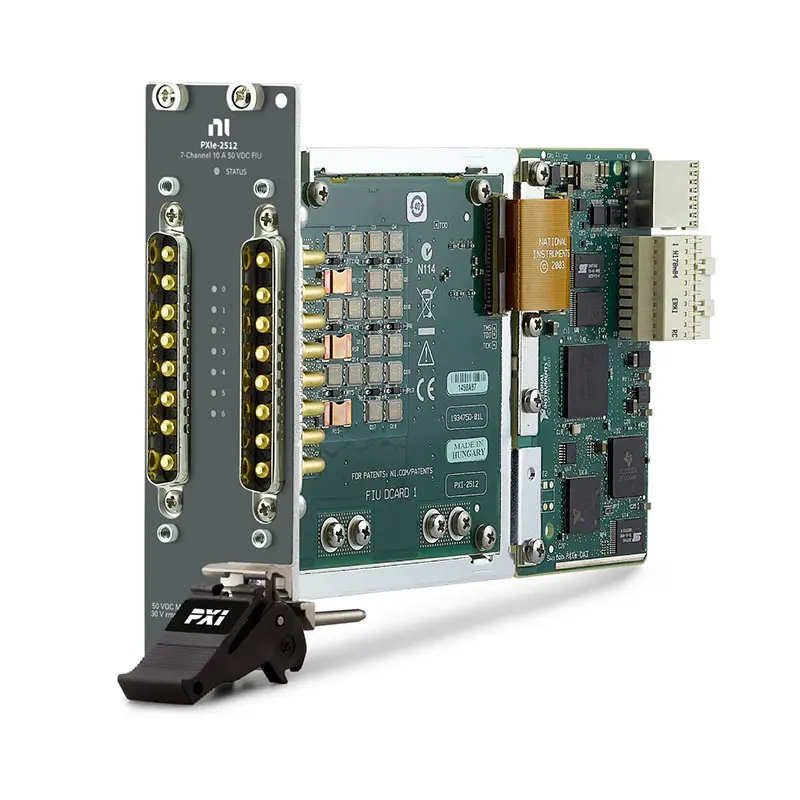
PXIe-2512 7-Channel Fault Insertion Switch Module
Земля PXIe-2512 is a seven-channel PXI Express signal insertion switch module designed for hardware-in-the-loop testing, electronic reliability testing and control-system validation. It operates as a fault insertion unit that can simulate open circuits, interrupted connections, pin-to-pin shorts, shorts to battery voltage and shorts to ground.
Each channel provides a feedthrough path between a test system and the device under test. The PXIe-2512 can open this connection or route the DUT side to one or more fault buses. Its FET switching architecture supports 10 A continuous current, fast operation and low path resistance for automotive, aerospace and industrial controller testing.
Key Features of the PXIe-2512
- Seven independent fault insertion channels
- 10 A continuous switching and carry current per channel
- 50 A maximum pulsed current for up to 600 µs
- 50 VDC or 30 Vrms maximum switching voltage
- 500 W maximum switching power per channel
- Open-circuit fault simulation
- Pin-to-pin short simulation
- Short-to-battery and short-to-ground simulation
- Two configurable fault-bus connections
- FET solid-state switching technology
- 16 mΩ typical DC path resistance
- Greater than 800 kHz typical bandwidth
- 8 µs typical switching time
- Overcurrent and overtemperature protection
- PXI hardware trigger support
- LabVIEW Real-Time and NI-SWITCH compatibility
PXIe-2512 Technical Specifications
| Product Model | PXIe-2512 |
|---|---|
| Part Number | 780587-12 |
| Product Type | PXI Express Signal and Fault Insertion Switch Module |
| Number of Channels | 7 independent channels |
| Topology | Independent fault insertion unit channels |
| Maximum Switching Voltage | 50 VDC or 30 Vrms, CAT I |
| Maximum Continuous Current | 10 A per channel or common |
| Maximum Pulsed Current | 50 A for up to 600 µs |
| Maximum Switching Power | 500 W per channel |
| Typical DC Path Resistance | 16 mΩ |
| Maximum DC Path Resistance | 35 mΩ |
| Пропускная способность | Greater than 800 kHz typical in a 50 Ω system |
| Typical Switching Time | 8 µs |
| Maximum Switching Time | 35 µs |
| Switch Type | FET solid-state switch |
| Typical Switch Life | Unlimited when operated within specified limits |
| Typical Overcurrent Detection Limit | 10.5 A |
| Overcurrent Detection Delay | 20 ms |
| Input Trigger Sources | PXI trigger lines 0 through 7 |
| Minimum Trigger Pulse Width | 150 ns |
| Front Connectors | 2 × 8-position male D-Sub |
| Operating Temperature | 0°C to 50°C |
| Dimensions | 3U, two-slot PXI Express module |
| Weight | 403 g |
| Шинный интерфейс | PXI Express |
PXIe-2512 Part Number and Accessories
| Item | Part Number | Описание |
|---|---|---|
| PXIe-2512 | 780587-12 | Seven-channel, 10 A PXI Express fault insertion switch module |
| DB8F-DB8F-40A Cable | 781092-01 | 1 m, 8-pin female D-Sub to 8-pin female D-Sub switch cable |
| DB8F-Bare Wire-40A Cable | 781092-02 | 8-pin female D-Sub to bare-wire cable for custom fixtures |
The PXIe-2512 has two front-panel D-Sub connectors. Verify the required number of cables, connector gender, current rating and fixture wiring before ordering.
Fault Insertion Unit Architecture
A fault insertion unit is installed between the test system and the device under test. During normal operation, each PXIe-2512 channel provides a feedthrough connection between the channel input and the corresponding DUT connection.
During a fault test, software can interrupt the feedthrough path or connect the DUT side to a fault bus. This allows the test system to evaluate how an electronic controller responds to wiring and electrical faults without manually modifying the harness.
Seven Independent Fault Channels
The PXIe-2512 provides seven independently controlled channels. Each channel includes connections for the signal source, DUT and fault buses, allowing different fault conditions to be applied to individual control-system signals.
Multiple modules can be installed in a PXI Express system when the test application requires fault insertion across more than seven signal lines.
Open-Circuit Fault Simulation
The feedthrough switch can be opened to simulate a broken wire, disconnected sensor, loose connector or interrupted control signal. This allows engineers to verify that the controller detects the missing connection and activates the expected diagnostic response.
Open-circuit testing is commonly used to validate diagnostic trouble codes, warning indicators, fallback operating modes and system recovery behavior.
Pin-to-Pin Short Simulation
Two or more DUT channels can be connected to the same fault bus to simulate a short between pins. This helps test the controller’s response when separate sensor, actuator or communication lines become electrically connected.
Before creating a pin-to-pin short, verify that the connected sources will not exceed the voltage, current or switching-power limits of the module or device under test.
Short-to-Battery Simulation
A fault bus can be connected to an external battery or supply voltage. Individual DUT channels can then be switched to this bus to simulate a wire or signal pin shorted to battery voltage.
This capability is useful for automotive ECU, aircraft controller and industrial control-system validation. The applied voltage must remain within the PXIe-2512 maximum switching rating.
Short-to-Ground Simulation
Connecting a fault bus to ground allows the PXIe-2512 to simulate short-to-ground conditions. Engineers can verify whether a controller detects the fault, limits output current and enters the required protective state.
The test fixture should include appropriate external protection when the DUT or connected power source can deliver current beyond the module’s specified limits.
10 A Continuous Current Capability
The PXIe-2512 can continuously switch or carry as much as 10 A through each channel or common connection. This makes it suitable for higher-current controller signals, actuators, lamps, motors and other loads that cannot be handled by lower-current fault insertion modules.
Current ratings depend on correct connector selection, cable construction, chassis cooling and fixture wiring. All external components in the current path must be rated for the expected load.
50 A Pulsed Current
The module supports pulsed current up to 50 A for a maximum duration of 600 µs. This capability helps accommodate short-duration inrush events produced by capacitive loads, lamps and certain actuators.
The permissible pulse duration decreases as inrush and steady-state current increase. Repetitive pulse applications should be checked against the official current-pulse and thermal limits.
Low Path Resistance
The FET signal path provides typical DC resistance of 16 mΩ and a maximum of 35 mΩ. Low resistance reduces voltage drop and power dissipation when carrying higher current.
At the maximum 10 A continuous current, cable, connector and fixture resistance should also be considered because these components contribute to the total voltage drop and heat generation.
Fast FET Switching
The PXIe-2512 uses solid-state FET switches instead of electromechanical relays. Typical switching time is 8 µs, with a specified maximum of 35 µs.
Fast switching enables rapid fault application and removal during dynamic HIL test sequences. FET technology also avoids the mechanical wear associated with conventional relay contacts.
Overcurrent Protection
The module includes overcurrent detection with a typical threshold of 10.5 A and a detection delay of 20 ms. If a channel exceeds the supported current for too long, the module reports an overcurrent fault condition.
Overcurrent detection is an additional protection feature and should not replace appropriately rated fuses, current-limited power supplies or external protection in the test fixture.
Overtemperature Protection
Internal temperature monitoring protects the FET channels against excessive thermal stress. An overtemperature condition may occur when switching large capacitive or inductive loads or when high-energy signals are switched more frequently than the module can dissipate the generated heat.
When a thermal fault occurs, review the current waveform, switching frequency, chassis cooling and surrounding ambient temperature before restarting the test.
Front-Panel Status Indicators
The PXIe-2512 provides status indicators for module operation and individual DUT channels. The indicators show feedthrough operation, fault-bus routing and detected overcurrent or overtemperature conditions.
These indicators help engineers identify the active fault state during system setup, debugging and maintenance.
Hardware Triggering
The module supports input and output triggers through PXI trigger lines 0 through 7. Hardware triggering allows fault insertion events to be synchronized with other PXI instruments, real-time controllers and test-system events.
This deterministic coordination is valuable when a fault must be applied at a precise point in an ECU control cycle or hardware-in-the-loop simulation.
Typical PXIe-2512 Applications
- Automotive ECU hardware-in-the-loop testing
- Full authority digital engine control validation
- Aerospace controller reliability testing
- Electronic control-unit diagnostic testing
- Short-to-battery fault simulation
- Short-to-ground fault simulation
- Open-wire and broken-connection simulation
- Pin-to-pin short testing
- Actuator and load-control validation
- Industrial controller safety testing
- Production end-of-line testing
Automotive ECU Testing
The PXIe-2512 is well suited for validating automotive controllers connected to sensors, actuators, lamps, motors and other vehicle electrical systems. Test sequences can insert faults and verify whether the ECU records the correct diagnostic code and enters a safe operating mode.
Its 10 A capability is useful for channels that carry more current than typical sensor and communication signals.
Aerospace and FADEC Validation
Fault insertion testing can verify how a FADEC or other aerospace controller responds to disconnected sensors, shorted wires and abnormal supply conditions. Deterministic control through a PXI Express system allows faults to be coordinated with a real-time simulation.
The complete test system must follow the relevant aerospace safety, isolation and fixture-design requirements.
LabVIEW Real-Time Integration
The PXIe-2512 can be controlled through a PXI real-time system using the LabVIEW Real-Time Module. A real-time controller can apply and remove faults at deterministic points within a hardware-in-the-loop test sequence.
LabVIEW Real-Time can also coordinate the module with simulation models, data acquisition hardware, CAN interfaces and other PXI instruments.
NI-SWITCH Software Support
The PXIe-2512 is controlled through the NI-SWITCH instrument driver. NI-SWITCH provides functions for opening feedthrough channels, connecting DUT channels to fault buses, configuring triggers and monitoring channel status.
The driver supports LabVIEW, LabWindows/CVI and compatible text-based programming environments.
NI Switch Executive Integration
NI Switch Executive allows developers to define fault routes using meaningful signal and route names. This can simplify systems containing multiple PXIe-2512 modules and large ECU wiring harnesses.
Named routes make test sequences easier to read and reduce the need to directly manage every physical switch connection in application code.
PXI Express Chassis Integration
The PXIe-2512 occupies two slots in a compatible PXI Express chassis. The additional width supports the module’s higher-current FET circuitry and front-panel connectors.
Before installation, confirm that two adjacent slots are available and verify chassis cooling, controller compatibility and the required NI-SWITCH software version.
PXIe-2512 Troubleshooting
The module is not detected in NI MAX
Confirm that the PXIe-2512 is fully installed in two compatible adjacent slots. Check chassis power, PXI controller communication and NI-SWITCH installation, then restart NI Measurement & Automation Explorer.
A channel does not provide normal feedthrough
Verify that the CH and DUT connections are correctly wired and that the feedthrough path is commanded closed. Check the front-panel channel indicator and inspect the cable and test fixture.
The module reports an overcurrent condition
Disconnect the load and confirm that the channel current remains within the 10 A continuous rating. Check for wiring shorts, excessive inrush current and an incorrectly configured fault-bus voltage.
The module reports an overtemperature condition
Stop the switching sequence and allow the module to cool. Check chassis airflow, fan settings, current waveform, switching frequency and the load’s capacitive or inductive characteristics.
The short-to-battery test does not work
Confirm that the external battery or supply is connected to the correct fault bus and shares the required reference with the DUT. Verify the commanded route and ensure that the supply voltage remains within the module rating.
The short-to-ground test does not work
Verify that the selected fault bus is correctly connected to the intended ground reference. Check cable continuity, route configuration and the electrical relationship between the test system and DUT grounds.
The fault timing is not repeatable
Use PXI hardware triggers and deterministic real-time control instead of relying only on nondeterministic software timing. Confirm the trigger source, trigger line and test-sequence synchronization.
PXIe-2512 Comparison
| Модель | Primary Configuration | Best Suited For |
|---|---|---|
| PXIe-2512 | 7 channels, 10 A, 50 V, FET switching | Fast medium-to-high-current fault insertion |
| PXIe-2514 | 7 channels, 40 A, 28 V, FET switching | Very-high-current, low-voltage fault insertion |
| PXIe-2515 | 32-channel fault insertion architecture | Applications requiring additional channel density |
| PXI-2510 | 68 channels, 2 A, 150 V, electromechanical relays | High-channel-count and higher-voltage fault simulation |
| PXI-2512 | 7 channels, 10 A, PXI hybrid interface | Maintaining existing PXI-based HIL systems |
Recommended Related Products
- PXIe-2514 7-Channel 40 A Fault Insertion Switch Module
- PXIe-2515 32-Channel Fault Insertion Switch Module
- PXI-2510 68-Channel Fault Insertion Switch Module
- PXI-2512 7-Channel Fault Insertion Switch Module
- View More NI PXI and PXI Express Modules
Selecting the Right Fault Insertion Module
Choose the PXIe-2512 when the application requires seven channels, fast solid-state switching and continuous currents up to 10 A. It provides a useful balance between current capacity, switching speed and supported voltage.
Select the PXIe-2514 for loads requiring up to 40 A at lower voltage. Consider the PXIe-2515 or PXI-2510 when channel density is more important than maximum current per channel.
PXIe-2512 vs PXIe-2514
Both modules provide seven-channel FET-based fault insertion. The PXIe-2512 supports up to 10 A and 50 VDC, while the PXIe-2514 supports higher current up to 40 A but has a lower maximum switching voltage of 28 VDC.
The PXIe-2512 is appropriate for a wider range of medium-current controller signals. The PXIe-2514 is intended for high-current automotive and power-load applications operating within its lower voltage limit.
Why Choose the PXIe-2512?
- Simulates common wiring and electrical faults automatically
- Supports seven independently controlled channels
- Handles continuous current up to 10 A
- Provides 50 A short-duration pulse capability
- Offers fast 8 µs typical FET switching
- Includes overcurrent and overtemperature protection
- Supports PXI hardware triggering and real-time control
- Integrates with NI-SWITCH and NI Switch Executive
Frequently Asked Questions
What is the PXIe-2512?
The PXIe-2512 is a seven-channel PXI Express fault insertion switch module used to simulate open circuits, pin shorts, short-to-battery and short-to-ground conditions.
What is the maximum continuous current?
The module can continuously switch or carry up to 10 A through each channel or common connection.
Can the PXIe-2512 handle inrush current?
Yes. It supports pulsed current up to 50 A for a maximum duration of 600 µs, subject to its pulse-width and thermal limitations.
What is the maximum switching voltage?
The maximum switching voltage is 50 VDC or 30 Vrms for Measurement Category I signal circuits.
Does the PXIe-2512 use mechanical relays?
No. It uses FET solid-state switches, providing fast switching, low path resistance and no mechanical contact wear when operated within specification.
How does the module simulate an open circuit?
The PXIe-2512 opens the normal feedthrough connection between the channel input and DUT connection, simulating a broken or disconnected wire.
How does it simulate a pin-to-pin short?
Two DUT channels are connected to the same external fault bus, creating an electrical connection between the selected pins.
Which cables are compatible with the PXIe-2512?
Compatible options include the DB8F-DB8F-40A cable, part number 781092-01, and the DB8F-Bare Wire-40A cable, part number 781092-02.
What is the PXIe-2512 part number?
The standard NI part number for the PXIe-2512 is 780587-12.
Request a Quote for the PXIe-2512
Contact us for current availability, lead time and project pricing for the PXIe-2512 7-Channel 10 A Fault Insertion Switch Module. We can also help identify compatible DB8 cables, PXI Express chassis and related fault insertion modules for your HIL system.















