







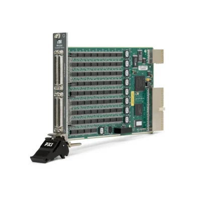
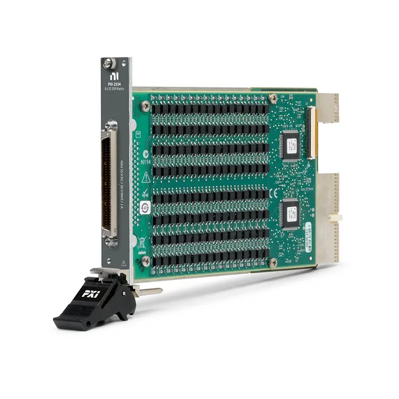
PXI-2534 256-Crosspoint 8×32 PXI Matrix Switch Module
Земля PXI-2534 is a high-density, 256-crosspoint PXI matrix switch module designed for automated test, signal routing and electronic validation systems. Its 1-wire 8 × 32 matrix architecture allows any of eight rows to be connected to any of 32 columns.
The PXI-2534 uses solid-state relays instead of conventional electromechanical contacts. This architecture provides fast operation, no mechanical contact wear and the ability to activate all 256 crosspoints simultaneously when the module is operated within its electrical and thermal specifications.
Key Features of the PXI-2534
- 1-wire 8 × 32 matrix topology
- 256 independently controlled crosspoints
- Solid-state relay switching architecture
- 55 VDC or 30 VAC maximum switching voltage
- 1 A maximum switching and carry current
- 55 W maximum switching power per crosspoint
- Greater than 2 MHz typical single-crosspoint bandwidth
- 1 Ω typical total row-to-column path resistance
- 400 crosspoints/s maximum scan rate under specified conditions
- 724 µs typical solid-state relay operate time
- All 256 relays can be driven simultaneously
- Unlimited expected relay life within specified limits
- PXI hardware input and output trigger support
- Onboard relay-count tracking
- 68-pin male SCSI front-panel connector
- PXI hybrid-slot compatibility
- NI-SWITCH and NI Switch Executive support
PXI-2534 Technical Specifications
| Product Model | PXI-2534 |
|---|---|
| Part Number | 778572-34 |
| Product Type | PXI solid-state matrix switch module |
| Topology | 1-wire 8 × 32 matrix |
| Number of Rows | 8 |
| Number of Columns | 32 |
| Number of Crosspoints | 256 |
| Number of Banks | 1 |
| Тип реле | Solid-state relay, SSR/FET |
| Maximum Switching Voltage | ±55 VDC or 30 VACrms |
| Maximum Switching Current | 1 A per crosspoint |
| Maximum Carry Current | 1 A per crosspoint |
| Maximum Switching Power | 55 W per crosspoint |
| Typical Total Path Resistance | 1 Ω, row to column |
| Maximum Total Path Resistance | 1.4 Ω |
| Typical DC Isolation Resistance | Greater than 2 GΩ |
| Typical Single-Crosspoint Bandwidth | Greater than 2 MHz in a 50 Ω system |
| Typical Crosstalk at 10 kHz | Less than −45 dB |
| Typical SSR Operate Time | 724 µs |
| Maximum SSR Operate Time | 2,5 мс |
| Maximum Scan Rate | 400 crosspoints/s when switching less than 20 V at 1 A |
| Simultaneous Drive Limit | 256 relays |
| Expected Relay Life | Unlimited when operated within specified limits |
| Input Trigger Sources | PXI trigger lines 0 through 7 |
| Minimum Input Trigger Pulse Width | 70 ns |
| Output Trigger Destinations | PXI trigger lines 0 through 7 |
| Output Trigger Pulse Width | Programmable from 1 µs to 62 µs |
| I/O Connector | 68-pin male SCSI |
| Шинный интерфейс | PXI hybrid |
| Module Format | 3U, one-slot PXI/cPCI module |
| Dimensions | 21.6 × 2.0 × 13.0 cm |
| Weight | 238 g |
| Operating Temperature | 0°C to 55°C |
| Storage Temperature | −40°C to 70°C |
| Maximum Altitude | 2,000 m |
| Поддержка программного обеспечения | NI-SWITCH and NI Switch Executive |
PXI-2534 Part Number and Accessories
| Item | Part Number | Описание |
|---|---|---|
| PXI-2534 | 778572-34 | 256-crosspoint, 1-wire 8 × 32 PXI solid-state matrix switch |
| TB-2637 | 780271-01 | Front-mount terminal block designed for the PXI-2534 8 × 32 matrix; no longer available from NI |
| TBX-68 | 777141-01 | 68-pin male SCSI remote connector block |
| SH68-68-S Cable | 185262-01 | 1 m shielded 68-pin SCSI switch cable |
| SH68-68-S Cable | 185262-02 | 2 m shielded 68-pin SCSI switch cable |
| SH68-68-S Cable | 185262-05 | 5 m shielded 68-pin SCSI switch cable |
The original TB-2637 front-mounted terminal block is listed by NI as no longer available. Buyers maintaining an existing PXI-2534 system should verify whether the required terminal block is already installed or whether compatible cable, connector-block or custom-fixture wiring is available before ordering the module.
1-Wire 8 × 32 Matrix Architecture
The PXI-2534 contains eight rows, 32 columns and 256 independently controlled crosspoints. Closing a crosspoint connects the selected row to the selected column, allowing software to establish flexible routes between instruments, signal sources, loads and devices under test.
Unlike a multiplexer, which normally connects one selected channel to a common terminal, the matrix architecture can establish multiple row-to-column routes simultaneously. This makes the PXI-2534 suitable for systems in which several instruments and test points must be interconnected dynamically.
256 Independently Controlled Crosspoints
Every intersection between the eight rows and 32 columns contains a solid-state switching element. Test software can open or close these crosspoints individually to create the required routing pattern.
The module supports simultaneous activation of all 256 crosspoints when the electrical, thermal and signal-source limitations of the complete system are observed. Before closing multiple routes, verify that the configuration does not connect incompatible sources or create unintended parallel paths.
Solid-State Relay Technology
The PXI-2534 uses solid-state relays rather than electromechanical contacts. Because there are no moving contacts, the switching elements do not have a mechanically limited cycle life when they are operated within specification.
Solid-state technology also provides faster switching than many general-purpose armature-relay modules. However, solid-state switches have measurable on-resistance, leakage and capacitance, which should be considered when routing precision or higher-frequency signals.
Unlimited Expected Relay Life
NI specifies unlimited expected relay life when the PXI-2534 is operated within its voltage, current, power, temperature and switching-frequency limits. This makes the module suitable for production systems requiring frequent route changes.
The maximum permissible switching frequency may decrease as load voltage and current increase. Applications operating near the maximum electrical ratings should be checked against the official cycle-frequency derating information.
55 V and 1 A Switching Capability
The module supports switching voltages up to ±55 VDC or 30 VACrms and switching or carry current up to 1 A per crosspoint. Maximum switching power is 55 W per crosspoint.
Voltage, current and power ratings apply simultaneously. Connected sources and loads must remain within all applicable limits, including during startup, shutdown, inrush and transient conditions.
Simultaneous 55 W Signal Routing
The solid-state architecture allows the PXI-2534 to route supported signals through multiple crosspoints at the same time. This is useful for parallel automated tests that must connect several sources or measurement instruments simultaneously.
Although the module can drive all 256 relays, the test fixture must not create conflicts between voltage sources. Avoid closing routes that connect outputs with incompatible voltage levels, polarities or grounding arrangements.
Low Row-to-Column Path Resistance
The PXI-2534 provides approximately 1 Ω typical total path resistance from a row to a column, with a specified maximum of 1.4 Ω. This resistance includes the solid-state switching path and internal circuit traces.
Path resistance can cause voltage drop and power dissipation when routing current. At 1 A, consider the effect of the switch path as well as the resistance of cables, connectors and fixture wiring.
Greater Than 2 MHz Bandwidth
Typical single-crosspoint bandwidth is greater than 2 MHz in a 50 Ω system with one row connected to one column. This makes the PXI-2534 appropriate for DC, low-frequency and moderate-frequency signal routing.
Actual bandwidth depends on the number of active routes, cable construction, fixture layout, source impedance and load impedance. Matrix stubs and additional closed crosspoints can increase capacitance and reduce system bandwidth.
Fast Solid-State Switching
Typical SSR operate time is 724 µs, with a specified maximum of 2.5 ms. This enables rapid route changes during automated validation and production test sequences.
Some signals and measurement instruments require additional settling time after a route changes. Test software should allow sufficient delay for the switch path, signal source, load and measurement instrument to stabilize.
400 Crosspoints per Second Scan Rate
The PXI-2534 supports a maximum scan rate of 400 crosspoints per second when switching less than 20 V at 1 A. The allowed scan rate may be lower at higher switching voltages and currents because of thermal derating.
Complete test throughput also depends on trigger configuration, software execution, measurement aperture and device-under-test settling time. The crosspoint scan rate should not be interpreted as the total completed-measurement rate.
Hardware Triggering
The module accepts input triggers from PXI trigger lines 0 through 7 with a minimum pulse width of 70 ns. It can also route output triggers to PXI trigger lines 0 through 7 with a programmable pulse width from 1 µs to 62 µs.
Hardware triggering allows switch operations to be coordinated with digital multimeters, digitizers, data acquisition modules and other PXI instruments. This deterministic synchronization can improve repeatability and test throughput.
Onboard Relay-Count Tracking
The PXI-2534 includes onboard relay-count tracking for monitoring crosspoint activity. Although solid-state relays do not experience conventional mechanical contact wear, operation counts can help characterize route usage and diagnose test-system behavior.
Relay-count data can also help engineers identify heavily used signal paths, compare production stations and verify that automated switching sequences are operating as intended.
Typical PXI-2534 Applications
- High-channel-count automated test equipment
- Production functional testing
- Electronic device validation
- Semiconductor test signal routing
- Printed circuit board testing
- Instrument-to-DUT interconnection
- Power-supply and load routing
- Parallel measurement systems
- Design verification testing
- Reliability and life-cycle testing
- Laboratory automation
- Custom test-fixture routing
Automated Test Equipment
The PXI-2534 allows several instruments to share connections with multiple device-under-test nodes. A test sequence can automatically establish each required route without manual cable changes.
Its 256 crosspoints provide high routing density in one PXI slot, while solid-state switching supports applications with frequent route changes and long-duration production operation.
Production Functional Testing
Production systems can use the PXI-2534 to connect power supplies, measurement instruments and test resources to different product pins. Software-controlled routing enables one fixture to perform multiple test stages.
Hardware triggers can synchronize route changes with measurement operations, reducing software timing uncertainty and improving repeatability between tested units.
Parallel Measurement Systems
Because multiple crosspoints can be active simultaneously, the PXI-2534 can support parallel measurement and stimulus paths. This can improve throughput when several independent instruments and test points are used at the same time.
The route configuration must be reviewed carefully to prevent unwanted connections between instruments. Software route validation and clear signal naming are particularly important in matrix systems.
NI-SWITCH Software Support
The PXI-2534 is controlled through the NI-SWITCH instrument driver. NI-SWITCH provides functions for initializing the module, opening and closing crosspoints, creating scan lists, configuring triggers and reading relay-count information.
The driver supports LabVIEW, LabWindows/CVI and compatible text-based programming environments. Applications can control physical row and column connections directly or use higher-level named routes.
NI Switch Executive Integration
NI Switch Executive allows engineers to assign meaningful aliases to rows, columns and routes. Instead of addressing every physical crosspoint directly, test programs can request connections using descriptive signal names.
This approach can simplify large automated systems and reduce routing errors. Named routes also make test sequences easier to read, document and maintain when fixture wiring changes.
PXI Hybrid-Slot Integration
The PXI-2534 is a one-slot, 3U PXI module with a PXI hybrid bus connector. It can be installed in a compatible PXI chassis or PXI Express chassis hybrid slot.
Before installation, verify the chassis slot type, available cooling, controller compatibility and installed NI-SWITCH version. Chassis power must be turned off before installing or removing the module.
PXI-2534 Troubleshooting
The PXI-2534 is not detected in NI MAX
Confirm that the module is fully seated in a compatible PXI or PXI Express hybrid slot. Check chassis power, controller communication and the NI-SWITCH installation, then rescan the system in NI Measurement & Automation Explorer.
A row-to-column route does not close
Verify the row and column names used by the selected topology. Check the NI-SWITCH command, terminal connection and external fixture wiring. Confirm that the requested route does not conflict with another active connection.
The signal has an unexpected voltage drop
Consider the module’s row-to-column path resistance together with cable, connector and fixture resistance. Voltage drop becomes more significant as routed current increases.
The measured signal does not settle quickly
Add settling time after changing the matrix route. Check source impedance, load capacitance, external cable length, measurement aperture and the response time of the connected instrument.
The scan rate is lower than 400 crosspoints/s
The maximum rate applies under specified load conditions. Review the switched voltage, current and cycle-frequency derating requirements. Measurement and software timing may also reduce overall throughput.
High-frequency signals are attenuated
Reduce cable length, minimize unused stubs and review source and load impedance. Multiple active crosspoints and long fixture wiring can increase capacitance and reduce bandwidth.
The original TB-2637 terminal block is unavailable
NI currently lists the TB-2637 as no longer available. Confirm whether an existing terminal block can be reused or whether an appropriate shielded cable, connector block or professionally designed custom fixture is required.
PXI-2534 Comparison with Similar Matrix Modules
| Модель | Primary Topology | Best Suited For |
|---|---|---|
| PXI-2533 | 1-wire 4 × 64, 256 crosspoints | Applications requiring more columns and fewer rows |
| PXI-2534 | 1-wire 8 × 32, 256 crosspoints | Balanced high-density solid-state matrix routing |
| PXI-2532B | 512-crosspoint configurable matrix | Higher-density systems requiring multiple topology options |
| PXIe-2738 | 8 × 32 matrix | Newer PXI Express systems requiring an 8 × 32 architecture |
| PXIe-2739 | 16 × 16 matrix | Systems requiring an equal number of rows and columns |
PXI-2534 vs PXI-2533
Both modules provide 256 solid-state crosspoints, 1 A switching and unlimited expected relay life within specification. The PXI-2534 uses an 8 × 32 topology, while the PXI-2533 uses a 4 × 64 topology.
Choose the PXI-2534 when the system needs more instrument-side rows and fewer device-side columns. Choose the PXI-2533 when four rows and a larger group of 64 columns better match the test architecture.
PXI-2534 vs PXI-2532B
The PXI-2534 provides a fixed 8 × 32 topology with 256 solid-state crosspoints. The PXI-2532B provides 512 reed-relay crosspoints and supports several topologies through interchangeable terminal blocks.
Select the PXI-2534 for high-cycle applications that benefit from solid-state relays and 1 A switching. Consider the PXI-2532B when higher crosspoint density, additional topology choices or different signal-path characteristics are required.
Recommended Related Products
- PXI-2533 4 × 64 Solid-State Matrix Switch Module
- PXI-2532B 512-Crosspoint Matrix Switch Module
- PXIe-2738 8 × 32 Matrix Switch Module
- PXIe-2739 16 × 16 Matrix Switch Module
- PXIe-4080 Digital Multimeter
- View More NI PXI and PXI Express Modules
Selecting the Right PXI Matrix Module
Choose the PXI-2534 when the test system requires 256 crosspoints, an 8 × 32 topology, 1 A current capacity and frequent solid-state switching. It is particularly suitable for high-throughput systems that benefit from simultaneous crosspoint operation and the absence of mechanical contact wear.
Select the PXI-2533 when a 4 × 64 topology matches the fixture more closely. Consider the PXI-2532B when additional crosspoints and configurable topologies are required, or a PXIe-2738 when building a newer PXI Express matrix system.
Why Choose the PXI-2534?
- Provides 256 independently controlled crosspoints
- Offers a practical 1-wire 8 × 32 matrix topology
- Uses fast solid-state relay technology
- Has no mechanically limited relay life within specification
- Supports up to 55 VDC, 1 A and 55 W
- Allows all 256 relays to operate simultaneously
- Scans at up to 400 crosspoints per second
- Supports deterministic PXI hardware triggering
- Integrates with NI-SWITCH and NI Switch Executive
Frequently Asked Questions
What is the PXI-2534?
The PXI-2534 is a 256-crosspoint, 1-wire 8 × 32 PXI matrix switch module for high-density automated signal routing.
What is the PXI-2534 topology?
The module uses a fixed 1-wire 8 × 32 matrix topology with eight rows and 32 columns.
How many crosspoints does the PXI-2534 provide?
It provides 256 independently controlled crosspoints.
What type of relays does it use?
The PXI-2534 uses solid-state relays. These switches have no mechanically limited operating life when used within their specified limits.
What is the maximum switching voltage?
The maximum switching voltage is ±55 VDC or 30 VACrms between channels or between a channel and ground.
What is the maximum switching current?
The module supports switching and carry current up to 1 A per crosspoint.
What is the PXI-2534 bandwidth?
Typical single-crosspoint bandwidth is greater than 2 MHz in a 50 Ω system with one row connected to one column.
What is the maximum scan rate?
The maximum scan rate is 400 crosspoints per second when switching less than 20 V at 1 A. Other load conditions are subject to derating.
Can all crosspoints operate simultaneously?
Yes. The simultaneous drive limit is 256 relays, provided the complete routing configuration remains within the module’s electrical and thermal limits.
Which terminal block was designed for the PXI-2534?
The TB-2637, part number 780271-01, was designed for the PXI-2534 8 × 32 matrix. NI currently lists this terminal block as no longer available.
Which software controls the PXI-2534?
The module can be controlled with NI-SWITCH and integrated into named-route systems using NI Switch Executive.
What is the PXI-2534 part number?
The standard NI part number is 778572-34.
Request a Quote for the PXI-2534
Contact us for current availability, lead time and project pricing for the PXI-2534 256-Crosspoint 8 × 32 PXI Matrix Switch Module. We can also help identify available TB-2637 terminal blocks, compatible 68-pin connectivity, PXI chassis and alternative NI matrix switch modules for your automated test system.















