




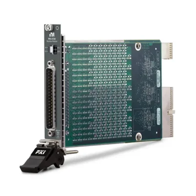
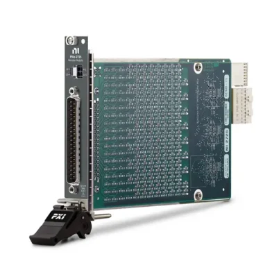
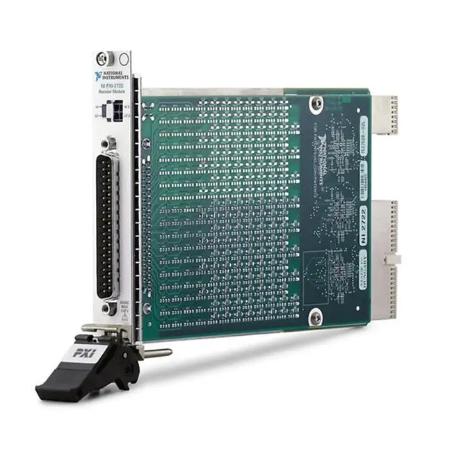
PXI-2722 16-Bit 5-Channel PXI Programmable Resistor Module
Земля ПХИ-2722 is a five-channel, 16-bit PXI programmable resistor module designed for sensor simulation, hardware-in-the-loop testing and automated control-system validation. Each channel provides software-programmable resistance with 0.25 Ω resolution and a specified resistance range from 0.25 Ω to 16,320 Ω.
The module uses discrete precision resistors and reed relays to create repeatable resistance values. It can simulate resistive sensors such as resistance temperature detectors, potentiometers and other variable-resistance devices without requiring a physical sensor at every test point.
With five independent channels, configurable bank connections and support for NI-SWITCH, NI-DAQmx and NI Switch Executive, the PXI-2722 provides a flexible platform for automotive, aerospace, industrial and electronic controller testing.
Key Features of the PXI-2722
- Five independently programmable resistor channels
- 16-bit resistor architecture per channel
- 0.25 Ω resistance resolution
- 0.25 Ω to 16,320 Ω specified resistance range
- Up to 16,383 Ω nominal programmable architecture
- 0.5% individual resistor accuracy
- 100 ppm/°C resistor temperature coefficient
- 60 VDC or 30 VACrms maximum signal voltage
- 0.3 A maximum current per channel
- 0.25 W maximum power per channel
- Reed-relay switching technology
- 250 µs relay operate and release time
- Configurable potentiometer and voltage-divider operation
- Integrated DMM test connector
- PXI hardware trigger support
- 37-pin D-Sub front-panel connector
- NI-SWITCH, NI-DAQmx and NI Switch Executive support
PXI-2722 Technical Specifications
| Product Model | ПХИ-2722 |
|---|---|
| Part Number | 781985-22 |
| Product Type | PXI programmable resistor module |
| Number of Channels | 5 |
| Channel Resolution | 16-битный |
| Resistance Resolution | 0.25 Ω |
| Specified Resistance Range | 0.25 Ω to 16,320 Ω per channel |
| Nominal Programmable Range | 0 Ω to 16,383 Ω in 0.25 Ω steps |
| Typical Minimum Channel Resistance | 2 Ω, including path resistance |
| Individual Resistor Accuracy | 0.5% |
| Resistor Temperature Coefficient | 100 ppm/°C |
| Maximum Signal Voltage | 60 VDC or 30 VACrms, CAT I |
| Максимальный ток | 0.3 A per channel |
| Maximum Power | 0.25 W per channel |
| Тип реле | Reed relay |
| Relay Operate and Release Time | 250 µs |
| Simultaneous Drive Limit | 89 relays |
| Input Trigger Sources | PXI trigger lines 0 through 7 |
| Minimum Input Trigger Pulse Width | 150 ns |
| Output Trigger Destinations | PXI trigger lines 0 through 7 |
| Typical Output Trigger Pulse Width | 2 µs |
| Main Front Connector | 37-pin D-Sub |
| DMM Test Connector | 2 × 2 Micro-Fit connector |
| Operating Temperature | 0°C to 55°C |
| Storage Temperature | -20°C to 70°C |
| Operating Humidity | 5% to 85%, noncondensing |
| Maximum Operating Altitude | 2,000 m |
| Dimensions | 21.6 × 2.0 × 13.0 cm |
| Weight | 266 g |
| Module Format | 3U, one-slot PXI/CompactPCI module |
The module’s nominal relay architecture can generate values from 0 Ω through 16,383 Ω. The official specified resistance range is 0.25 Ω to 16,320 Ω, and the practical minimum output also includes relay, connector and PCB path resistance.
PXI-2722 Part Number and Accessories
| Item | Part Number | Описание |
|---|---|---|
| ПХИ-2722 | 781985-22 | Five-channel, 16-bit PXI programmable resistor module |
| SH37F-37M Cable | 778621-01 | 1 m shielded 37-pin female-to-male D-Sub cable |
| SH37F-37M Cable | 778621-02 | 2 m shielded 37-pin female-to-male D-Sub cable |
| CB-37F-HVD | 779491-01 | DIN-rail-mount 37-pin terminal block |
| TB-37F-37SC | 779184-01 | 37-pin D-Sub solder-cup accessory for custom wiring |
| TB-37F-37CP | 779185-01 | 37-pin D-Sub crimp-and-poke accessory for custom wiring |
| PXI-272x DMM Test Cable | 782465-01 | 2 × 2 Micro-Fit cable for resistance verification with a DMM |
| Relay Replacement Kit | 781451-10 | Package of ten compatible replacement reed relays |
Select the cable and terminal accessory according to the required fixture design, shielding, mounting arrangement and field-wiring method. The separate DMM connector is intended for verification and calibration-related measurements rather than the primary DUT connection.
Five-Channel Programmable Resistor Architecture
The PXI-2722 contains five independently controlled 16-bit resistor channels. Each channel is formed by combining two adjacent eight-bit resistor banks through programmable reed relays.
The lower bank contains binary-weighted resistance elements ranging from R through 128R. The upper bank contains elements ranging from 256R through 8192R, where R equals 0.25 Ω. Software closes the appropriate relay combinations to produce the requested nominal resistance.
This binary-weighted architecture provides a large number of repeatable resistance settings without requiring a mechanically adjusted potentiometer.
0.25 Ω Resistance Resolution
Each PXI-2722 channel can be programmed in nominal 0.25 Ω increments. Fine resistance resolution is particularly valuable when simulating temperature sensors or testing controller thresholds that respond to relatively small changes in resistance.
The requested nominal value should not be confused with the exact resistance measured at the front connector. Relay resistance, PCB traces, cable resistance, connector resistance and resistor tolerance all contribute to the actual value presented to the DUT.
Resistance Range and Accuracy
The specified resistance range extends from 0.25 Ω to 16,320 Ω per channel. This wide range allows one module to simulate low-resistance RTDs as well as higher-resistance sensors and control inputs.
Typical channel accuracy varies with the programmed resistance:
| Programmed Resistance | Typical Channel Accuracy |
|---|---|
| 20 Ω to 40 Ω | Less than 10% |
| 40 Ω to 120 Ω | Less than 5% |
| 120 Ω to 400 Ω | Less than 2% |
| 400 Ω to 16,000 Ω | Less than 1% |
Low programmed values are more strongly affected by the fixed resistance of relays and signal paths. Applications requiring precise absolute resistance should measure the complete channel and compensate for its actual path resistance.
Reed-Relay Switching
The PXI-2722 uses reed relays to connect its discrete resistor elements. Reed relays provide electrical isolation and low leakage, making them suitable for programmable resistance and sensor-simulation applications.
The specified relay operate and release time is 250 µs. The module supports up to 89 simultaneously driven relays, which must be considered when creating custom relay configurations or controlling multiple resistor banks directly.
Typical relay life is approximately 100 million cycles when switching low-power loads below 50 mW and approximately one million cycles at full-power loads below 250 mW. Actual service life depends on voltage, current, load type, switching frequency and transient energy.
Power-On and Reset State
Each PXI-2722 channel enters an open-circuit condition when the module powers up or is reset. This prevents an unintended resistance from automatically appearing across the DUT during system startup.
Test software should explicitly configure every required resistance after initializing or resetting the module. The application should also define safe behavior for driver errors, chassis power loss and emergency shutdown conditions.
Potentiometer and Voltage-Divider Configuration
The two resistor banks associated with each 16-bit channel can be interconnected through programmable bank-connect relays. This allows the PXI-2722 to implement more than a simple two-terminal resistor.
Depending on the wiring and relay configuration, the banks can form a programmable potentiometer, voltage divider or multi-segment resistor chain. These configurations are useful for simulating sensors that provide a divided voltage rather than a simple resistance.
When using a voltage-divider configuration, verify the voltage, current and power dissipated by every resistor segment. The complete circuit must remain within the module’s 60 VDC, 0.3 A and 0.25 W per-channel limits.
RTD Temperature Sensor Simulation
A resistance temperature detector changes resistance predictably as temperature changes. The PXI-2722 can reproduce selected RTD resistance values so that a controller believes it is connected to a sensor at a particular temperature.
Software can convert a requested temperature into the corresponding RTD resistance and program the appropriate channel value. Automated tests can then sweep through normal temperatures, boundary values and fault conditions while monitoring the controller response.
For high-accuracy RTD simulation, account for the module’s path resistance and the external cable resistance. The applicable RTD curve, lead configuration and controller excitation current must also be considered.
Potentiometer Sensor Simulation
Many throttle-position, valve-position, level and mechanical-position sensors behave like potentiometers. The PXI-2722 bank architecture can help emulate these devices by producing programmable resistance ratios or divided voltages.
Automated software can move the simulated sensor position through its operating range and verify that the device under test reports the expected position. Tests can also evaluate endpoint behavior, nonlinear transitions and out-of-range resistance conditions.
Thermistor and Resistive Sensor Simulation
The PXI-2722 can simulate many resistance-based sensors when their required values fall within the module’s operating range. A lookup table or mathematical model can convert the desired physical condition into a programmable resistance.
Possible applications include thermistor simulation, fluid-level sensors, pressure transducers with resistive outputs and industrial resistance transmitters. Verify the sensor’s excitation method and maximum current before connecting the module.
Hardware-in-the-Loop Testing
In a hardware-in-the-loop system, the PXI-2722 can replace physical resistive sensors connected to an electronic controller. A real-time simulation calculates the required sensor state, and the module creates the corresponding electrical resistance.
This approach allows the test system to reproduce operating conditions that would otherwise require environmental chambers, mechanical movement or a complete physical machine. It can also simulate rapid transitions and repeat identical resistance profiles across many test runs.
Automotive ECU Testing
Automotive controllers commonly monitor temperature, position and fluid-level sensors through resistance or divided-voltage inputs. The PXI-2722 can simulate these inputs during ECU design validation, production testing and diagnostic verification.
A test sequence can check whether the ECU correctly converts resistance into an engineering value, detects implausible readings and activates the expected diagnostic trouble code when the simulated sensor moves outside its valid range.
Aerospace Controller Validation
Aircraft controllers and avionics systems use resistance-based sensors for temperature, position and system-status monitoring. The PXI-2722 can reproduce these sensor values within an automated PXI test platform.
The module can support repeatable verification of input accuracy, warning thresholds, redundancy logic and fault-management behavior. The complete test fixture must follow the applicable isolation, safety and certification requirements.
Industrial Control-System Testing
Industrial controllers, data loggers and monitoring systems frequently accept RTD, potentiometer and resistance inputs. The PXI-2722 provides software-controlled resistance for validating these input channels without manually changing resistor decade boxes.
Automated testing can cover calibration points, alarm limits, open-circuit conditions and response across the controller’s full measurement range.
Integrated DMM Test Connection
The front panel includes a 2 × 2 Micro-Fit DMM connector that provides access to adjacent even and odd resistor-bank pairs. This connection helps engineers verify channel resistance or voltage without disturbing the main 37-pin DUT wiring.
For accurate low-resistance measurements, NI recommends a compatible DMM with Offset Compensated Ohms capability, such as the PXI-4070, PXI-4071 или PXI-4072.
Closing several DMM test-relay pairs at the same time can create unintended low-impedance paths between channels. Disconnect the primary 37-pin cable when a connected DUT could be damaged by these paths.
Hardware Triggering
The PXI-2722 accepts input triggers from PXI trigger lines 0 through 7 and can route output triggers to those same backplane lines. Hardware triggers help coordinate resistor changes with data acquisition, controller events and other PXI instruments.
A minimum input pulse width of 150 ns is required. The typical generated output-trigger pulse width is 2 µs.
NI-272x Reference VIs
NI provides NI-272x Reference VIs that allow applications to request a resistance value or an RTD temperature rather than calculate every relay state directly. These reference VIs can simplify common resistor and sensor-simulation tasks.
The reference VIs use NI-DAQmx and are intended for convenient configuration. NI recommends using the NI-DAQmx API directly when relay control must run inside a time-critical loop.
NI-SWITCH and NI Switch Executive
The PXI-2722 can also be controlled with NI-SWITCH. The independent topology is identified in software as 2722/Independent, allowing applications to address the resistor banks, shunt relays and bank-connect relays.
NI Switch Executive can provide named routes and route groups for larger automated systems. Meaningful names can make test sequences easier to understand and reduce dependence on physical relay identifiers.
Electrical Load Protection
The maximum channel ratings are 60 VDC or 30 VACrms, 0.3 A and 0.25 W. All three limits must be respected simultaneously. A circuit below the voltage and current ratings can still exceed the maximum resistor power.
Inductive loads can generate high-voltage transients when a relay opens. Capacitive loads can create substantial inrush current when a relay closes. Use appropriate current limiting, flyback diodes, snubbers or transient protection when the connected circuit can exceed the relay ratings.
Installation Considerations
The PXI-2722 occupies one slot in a compatible PXI or hybrid-slot chassis. Verify chassis compatibility, cooling, controller support and the required NI software before installation.
Because the module contains magnetically operated reed relays, avoid installing it directly beside an embedded controller that contains a magnetic hard disk. Magnetic fields from the relays can interfere with susceptible storage devices.
Typical PXI-2722 Applications
- RTD temperature sensor simulation
- Potentiometer simulation
- Thermistor simulation
- Resistive sensor emulation
- Hardware-in-the-loop testing
- Automotive ECU validation
- Aerospace controller testing
- Industrial controller verification
- Electronic control-unit production testing
- Programmable voltage-divider construction
- Alarm and threshold verification
- Automated calibration systems
- Open-sensor fault simulation
- Resistance-input functional testing
PXI-2722 Test Workflow
Step 1: Define the Sensor Model
Determine the resistance or resistance ratio corresponding to each physical input condition. For RTDs and thermistors, use the correct sensor curve and coefficient data.
Step 2: Verify Electrical Limits
Calculate the controller’s excitation voltage, channel current and power dissipation. Confirm that the complete operating range stays within the PXI-2722 ratings.
Step 3: Connect the Test Fixture
Connect the DUT through a compatible SH37F-37M cable, terminal block or custom 37-pin D-Sub fixture. Check the pinout and channel connections before applying power.
Step 4: Measure Path Resistance
Use the DMM port or an external measurement path to characterize the actual channel resistance when the application requires compensation for relay and wiring resistance.
Step 5: Program the Resistance
Use the NI-272x Reference VIs, NI-DAQmx or NI-SWITCH to select the required channel value or custom bank configuration.
Step 6: Run the Automated Test
Change the resistance according to the test profile and record the DUT measurement, diagnostic status and response at each point.
PXI-2722 Troubleshooting
The PXI-2722 is not detected
Confirm that the module is fully inserted into a compatible PXI or hybrid slot. Check chassis power, controller communication and installation of the applicable NI driver. Restart NI Measurement & Automation Explorer if necessary.
The measured resistance is higher than programmed
The measured value includes relay, PCB, connector, cable and fixture resistance. Characterize the complete path and apply compensation when absolute resistance accuracy is important.
Low resistance values have poor accuracy
Fixed path resistance represents a larger percentage of a low programmed value. Use the DMM test connection to measure the actual channel resistance and avoid relying only on the nominal relay calculation.
The channel remains open circuit
Verify that the correct channel and topology are selected. Confirm that the application has configured the channel after initialization because every channel powers up and resets in the open state.
The resistance does not match the requested RTD temperature
Check the selected RTD type, reference resistance, temperature coefficient and conversion equation. Also account for channel and cable resistance, especially when simulating lower-resistance RTDs.
Relay life is shorter than expected
Check for excessive current, resistor power, capacitive inrush or inductive switching transients. Relay life decreases significantly when switching loads near the maximum power rating.
The DUT changes state during DMM testing
Multiple DMM test-relay connections can create unintended low-impedance paths. Disconnect the 37-pin DUT cable or isolate the DUT before configuring multiple DMM test paths.
Resistance changes are too slow for the test loop
Avoid using high-level reference VIs inside a time-critical loop. Use the appropriate NI-DAQmx or NI-SWITCH API and account for the 250 µs relay operate and release time.
PXI-2722 Comparison with Related Modules
| Модель | Architecture | Best Suited For |
|---|---|---|
| ПХИ-2720 | 10 channels, 8-bit, 0.25 Ω resolution | Higher channel count with a lower resistance range |
| ПХИ-2722 | 5 channels, 16-bit, 0.25 Ω resolution | Wide-range resistance and RTD simulation |
| PXIe-2725 | 18 channels, 8-bit, 0.25 Ω resolution | High-density low-range resistance simulation |
| PXIe-2727 | 9 channels, 16-bit, 0.25 Ω resolution | Higher-density wide-range PXI Express systems |
PXI-2722 vs PXI-2720
Земля ПХИ-2720 provides ten eight-bit programmable resistor channels, while the PXI-2722 provides five 16-bit channels. Both use 0.25 Ω base resolution, but the PXI-2722 provides a much wider resistance range per channel.
Choose the PXI-2720 when channel density is more important and the required resistance values fit within its lower range. Choose the PXI-2722 when fewer channels and resistance values up to approximately 16.32 kΩ are required.
PXI-2722 vs PXIe-2727
Земля PXIe-2727 provides nine 16-bit channels in a PXI Express module, while the PXI-2722 provides five 16-bit channels using the original PXI platform.
The PXIe-2727 is suitable for new systems requiring greater channel density. The PXI-2722 remains useful for maintaining existing PXI test systems or applications that specifically require its architecture and connector arrangement.
Recommended Related Products
- PXI-2720 10-Channel Programmable Resistor Module
- PXIe-2725 18-Channel Programmable Resistor Module
- PXIe-2727 9-Channel Programmable Resistor Module
- PXI-4070 Digital Multimeter
- PXI-4071 Digital Multimeter
- PXI-4072 Digital Multimeter and LCR Meter
- View More NI PXI and PXI Express Modules
Selecting the Right Programmable Resistor Module
Choose the PXI-2722 when the application requires five independently programmable channels, fine 0.25 Ω resolution and resistance values extending to approximately 16.32 kΩ. It is especially suitable for wide-range RTD, potentiometer and resistive-sensor simulation.
Choose an eight-bit module when the required range is lower and channel density is more important. Consider a PXI Express programmable resistor module when building a new system that requires additional channels.
Why Choose the PXI-2722?
- Provides five independent 16-bit resistor channels
- Offers fine 0.25 Ω programming resolution
- Covers resistance values up to 16.32 kΩ
- Supports RTD and potentiometer simulation
- Enables automated HIL sensor testing
- Provides configurable resistor-bank connections
- Includes a dedicated DMM verification connector
- Supports PXI hardware triggers
- Integrates with NI-SWITCH, NI-DAQmx and NI Switch Executive
- Fits existing PXI and compatible hybrid-slot systems
Frequently Asked Questions
What is the PXI-2722?
The PXI-2722 is a five-channel, 16-bit PXI programmable resistor module used for RTD, potentiometer and resistive-sensor simulation in automated test systems.
What is the resistance range of the PXI-2722?
The official specified resistance range is 0.25 Ω to 16,320 Ω per channel. Its binary relay architecture provides nominal settings extending from 0 Ω to 16,383 Ω in 0.25 Ω increments.
What is the resistance resolution?
The nominal resistance resolution is 0.25 Ω.
How many programmable channels are provided?
The PXI-2722 provides five independently programmable 16-bit resistor channels.
Can the PXI-2722 simulate an RTD?
Yes. Software can convert a requested temperature into the corresponding RTD resistance and program the module to simulate that sensor condition.
Can it simulate a potentiometer?
Yes. Its bank-connect architecture supports programmable potentiometer, voltage-divider and resistor-chain configurations.
What are the maximum electrical ratings?
The maximum ratings are 60 VDC or 30 VACrms, 0.3 A and 0.25 W per channel. All applicable limits must be observed simultaneously.
Why is the measured resistance different from the requested value?
The actual value includes resistor tolerance, relay resistance, PCB traces, connectors, cables and fixture wiring. Low requested values are particularly sensitive to this fixed path resistance.
Does the module have a DMM connection?
Yes. A dedicated 2 × 2 Micro-Fit connector provides DMM access for checking resistance or voltage across selected resistor-bank pairs.
Which software controls the PXI-2722?
The module can be controlled through NI-272x Reference VIs, NI-DAQmx, NI-SWITCH, NI Switch Executive and compatible IVI switch-driver applications.
What state do the channels enter at startup?
Every PXI-2722 channel powers up and resets in an open-circuit state.
What is the PXI-2722 part number?
The standard NI part number for the PXI-2722 is 781985-22.
Request a Quote for the PXI-2722
Contact us for current availability, lead time and project pricing for the PXI-2722 16-Bit 5-Channel PXI Programmable Resistor Module. We can also help identify compatible SH37F-37M cables, terminal blocks, DMM test cables, PXI chassis and related programmable resistor modules for your automated test system.















