






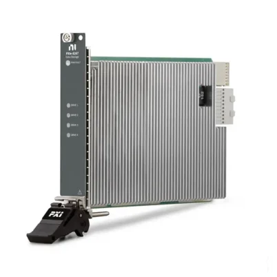
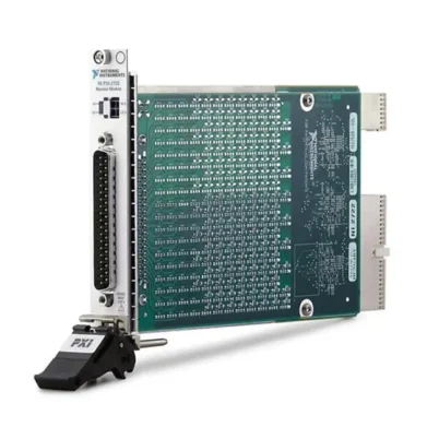
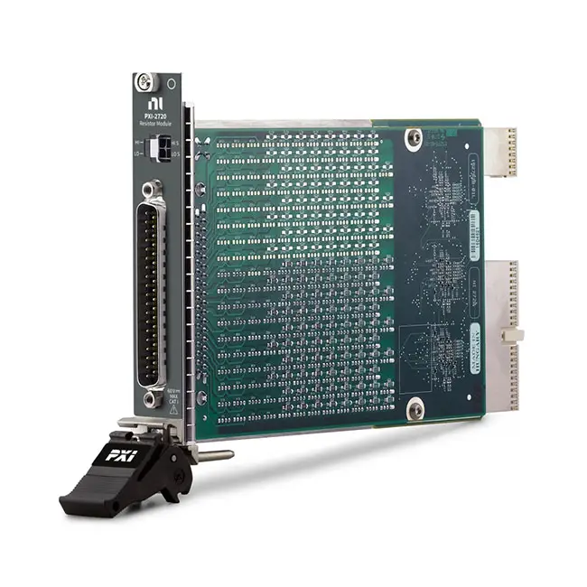
PXI-2720 10-Channel Programmable Resistor Module
Земля ПХИ-2720 is a 10-channel, 8-bit PXI programmable resistor module designed for sensor simulation, hardware-in-the-loop testing and automated electronic validation. Each independent channel can be programmed across a nominal resistance range of 1 Ω to 255 Ω in 1 Ω steps.
The module uses an electromechanical reed-relay network to place selected resistors into the signal path. This architecture allows the PXI-2720 to reproduce the behavior of resistance-based devices such as RTDs, potentiometers, resistive sensors, bridge elements and electronic control inputs.
Key Features of the PXI-2720
- 10 independent programmable resistor channels
- 8-bit resistance architecture per channel
- Nominal programmable range from 1 Ω to 255 Ω
- 1 Ω resistance resolution
- 60 VDC or 30 VACrms maximum channel voltage
- 300 mA maximum current per channel
- 0.25 W maximum power per channel
- 0.5% resistor-component accuracy
- 100 ppm/°C resistor temperature coefficient
- Reed-relay switching architecture
- Approximately 250 µs relay operating and release time
- PXI trigger-line support
- Integrated DMM test port
- 37-pin D-Sub signal connector
- One-slot 3U PXI format
- NI-SWITCH software support
- NI 272x Reference VI support
- NI VeriStand integration
PXI-2720 Technical Specifications
| Product Model | ПХИ-2720 |
|---|---|
| Part Number | 781985-20 |
| Product Type | PXI programmable resistor module |
| Number of Channels | 10 independent resistor channels |
| Bits per Channel | 8 bits |
| Nominal Resistance Range | 1 Ω to 255 Ω per channel |
| Resistance Resolution | 1 Ω |
| Typical Minimum Measured Resistance | Approximately 2 Ω, including relay and trace resistance |
| Resistor Accuracy | 0.5% |
| Temperature Coefficient | 100 ppm/°C |
| Maximum Channel-to-Channel Voltage | 60 VDC or 30 VACrms, CAT I |
| Maximum Channel-to-Ground Voltage | 60 VDC or 30 VACrms, CAT I |
| Максимальный ток | 300 mA per channel |
| Maximum Power | 0.25 W per channel |
| Тип реле | Electromechanical reed relay |
| Typical Relay Operating Time | 250 µs |
| Typical Relay Release Time | 250 µs |
| Typical Low-Power Relay Life | Up to 100 million cycles at loads below 50 mW |
| Typical Full-Power Relay Life | Up to 1 million cycles at loads below 250 mW |
| Input Trigger Sources | PXI trigger lines 0 through 7 |
| Minimum Trigger Pulse Width | 150 ns with digital filtering enabled |
| Output Trigger Destinations | PXI trigger lines 0 through 7 |
| Typical Output Trigger Pulse Width | 2 µs |
| Front Signal Connector | 37-pin D-Sub |
| DMM Port | 2 × 2 Micro-Fit connector |
| Power Requirement | 1.2 W at 3.3 V and up to 11 W at 5 V |
| Dimensions | 21.6 × 2.0 × 13.0 cm |
| Module Format | 3U, one-slot PXI/cPCI module |
| Weight | Approximately 266 g |
| Operating Temperature | 0°C to 55°C |
| Storage Temperature | -20°C to 70°C |
| Operating Humidity | 5% to 85% RH, noncondensing |
| Maximum Altitude | 2,000 m |
| Поддержка программного обеспечения | NI-SWITCH, NI 272x Reference VIs and NI VeriStand |
| Lifecycle Status | Discontinued |
PXI-2720 Part Number and Accessories
| Item | Part Number | Описание |
|---|---|---|
| ПХИ-2720 | 781985-20 | 10-channel, 8-bit PXI programmable resistor module |
| SH37F-37M Cable | 778621-01 | 1 m shielded 37-pin female-to-male D-Sub cable |
| SH37F-37M Cable | 778621-02 | 2 m shielded 37-pin female-to-male D-Sub cable |
| CB-37F-HVD | 779491-01 | High-voltage DIN-rail screw-terminal connector block |
| TB-37F-37CP | 779185-01 | 37-pin crimp-and-poke custom connectivity accessory |
| TB-37F-37SC | 779184-01 | 37-pin solder-cup D-Sub accessory with strain relief |
| DMM Test Cable | 782465-01 | 2 × 2 Micro-Fit to four banana-plug cable for four-wire resistance verification |
The 37-pin D-Sub interface connects the ten programmable resistor channels to the device under test. The separate DMM port allows an external digital multimeter to verify channel resistance through a four-wire measurement path.
10 Independent Programmable Resistor Channels
The PXI-2720 provides ten independently controlled resistance channels. Each channel contains a binary-weighted resistor and relay network that can be programmed without manually changing components or fixture wiring.
Different resistance values can be assigned to multiple channels during the same test. This allows one PXI module to simulate several sensors or resistive elements connected to an electronic controller.
8-Bit Resistor Architecture
Each channel uses an 8-bit resistor architecture. Binary-weighted resistor elements are connected by reed relays to create the requested nominal resistance.
An 8-bit channel provides 256 possible commanded states. The practical resistance includes the selected resistor value together with relay-contact and printed-circuit trace resistance.
1 Ω to 255 Ω Programmable Range
The nominal programmable range is 1 Ω to 255 Ω per channel with 1 Ω resolution. NI overview documents sometimes describe the logical range as 0 Ω to 255 Ω, but a true zero-ohm path is not physically available because the relays and circuit traces introduce residual resistance.
The actual minimum resistance measured at the front connector is typically around 2 Ω. Applications requiring very low resistance should include this offset in the calibration or simulation model.
1 Ω Resistance Resolution
Each channel can be commanded in 1 Ω increments. For example, software can request nominal values of 80 Ω, 100 Ω or 120 Ω according to the simulated sensor state.
The commanded step size is not the same as total measurement accuracy. Actual resistance also depends on resistor tolerance, relay and trace resistance, cable resistance, terminal-block resistance and temperature.
Relay and Path Resistance
The resistance appearing at the module connector includes the programmed resistor network plus DC offset resistance from the relay contacts and traces. This offset is especially significant when a low resistance is selected.
For precision simulation, measure each channel with an external DMM and apply channel-specific correction values in the test software. Four-wire measurement helps remove test-lead resistance from the verification result.
0.5% Resistor Accuracy
The resistor components have a specified accuracy of approximately 0.5%. Overall channel accuracy can be lower at small programmed values because fixed relay and path resistance represents a larger percentage of the total.
Accuracy improves proportionally as programmed resistance increases. The complete uncertainty calculation should include resistor tolerance, temperature effects and external wiring.
100 ppm Temperature Coefficient
The resistance elements have a temperature coefficient of approximately 100 ppm/°C. Resistance can therefore change as the internal module temperature or chassis environment changes.
Allow the PXI system to reach a stable operating temperature before performing precision tests. Calibration at the expected operating temperature can further reduce simulation error.
60 V Channel Rating
Each channel supports up to 60 VDC or 30 VACrms for CAT I signal circuits. This rating applies between channels and between a channel and ground under the specified operating conditions.
The module is not intended for connection to building mains or Measurement Category II, III or IV circuits. CAT I signals must also remain within the current and power limitations.
300 mA Maximum Channel Current
Each programmable resistor channel can carry up to 300 mA, provided the channel power remains at or below 0.25 W. Both conditions must be satisfied at the same time.
A current below 300 mA can still exceed the power limit when a larger resistance is selected. Calculate channel power using the expected current and programmed resistance before beginning the test.
0.25 W Maximum Channel Power
The maximum power is 0.25 W per channel. For a resistive channel, power can be calculated using either of the following relationships:
P = I²R или P = V²/R
For example, applying 300 mA through a 100 Ω resistance would theoretically dissipate 9 W, which is far beyond the module rating. The allowable current must be reduced as programmed resistance increases.
Resistive Sensor Simulation
The PXI-2720 can reproduce the resistance changes generated by sensors whose output is based on resistance. Test software can command a sequence of resistance values corresponding to temperature, position, pressure or another physical condition.
The controller under test interprets the programmed resistance as though a real sensor were connected. This makes tests repeatable and eliminates the need to expose physical sensors to every simulated condition.
RTD Simulation
Resistance temperature detectors change resistance according to temperature. The PXI-2720 can reproduce selected RTD resistance values within its supported range and 1 Ω resolution.
Software can accept a requested temperature, calculate the corresponding resistance from an RTD model and configure the channel. The 1 Ω step size must be evaluated against the temperature resolution required for the selected RTD type.
Potentiometer Simulation
Channels can be combined or configured within a fixture to reproduce aspects of a potentiometer or variable resistive load. Software can change resistance automatically as part of a test sequence.
Review the required three-terminal topology carefully. A single PXI-2720 channel is fundamentally a programmable resistance path, so external wiring may be required to reproduce the complete potentiometer circuit.
Voltage-Divider Simulation
Two programmable resistance channels can form a controllable voltage divider. The resulting voltage can simulate a sensor or control input whose output depends on the ratio between two resistors.
Both channel tolerances and offset resistances affect the divider ratio. The applied voltage and resulting power in each resistor channel must remain within the module ratings.
Bridge-Element Simulation
Multiple channels can be used in an external bridge circuit to simulate resistive bridge elements. This supports testing of strain, pressure and force measurement electronics.
The PXI-2720 does not provide sensor excitation or analog measurement. A separate power source and measurement instrument may be required to complete the bridge test system.
Hardware-in-the-Loop Testing
The module can simulate several resistive sensors connected to an ECU or industrial controller during an HIL test. Resistance values can change according to a real-time model, test step or inserted fault condition.
Test scenarios can represent normal operation, environmental changes, out-of-range sensor values and gradual resistance drift. The controller response can then be captured by other PXI measurement hardware.
Automated Production Testing
In production testing, the PXI-2720 can apply known resistance values to sensor-input circuits and verify whether the assembled product interprets them correctly. Ten channels support testing several inputs without manual component changes.
Automated resistance selection improves repeatability and allows a larger number of operating points to be tested within a production cycle.
Reed-Relay Switching
The resistor networks are configured using electromechanical reed relays. Reed relays provide low leakage and a physical contact path but have a finite operating life and switching time.
Typical relay operating and release time is approximately 250 µs. Application software should allow the resistance path to settle before performing a measurement or evaluating the device response.
Relay Life and Switched Load
Typical relay life can reach approximately 100 million cycles when switching low-power loads below 50 mW. At loads approaching the module’s 250 mW channel limit, typical life may decrease to approximately one million cycles.
Whenever possible, remove or reduce the applied signal before changing resistance. Switching a lower electrical load reduces contact wear and can extend relay life.
Onboard Relay-Count Monitoring
Relay operation counts can support preventive maintenance and help identify channels that experience unusually high switching activity. Frequently used simulation paths can be distributed among channels when the fixture design allows it.
Relay count alone does not determine remaining life because contact wear depends strongly on voltage, current, power and load characteristics.
Integrated DMM Test Port
The 2 × 2 Micro-Fit DMM port connects the channel test circuit to an external digital multimeter. This makes it possible to verify the programmed resistance without disconnecting every channel from the front-panel wiring.
The optional DMM test cable provides four banana plugs for a four-wire resistance measurement. Four-wire measurement reduces error caused by test leads and connector resistance.
Resistance Verification
For the most accurate verification, disconnect the external 37-pin DUT cable before connecting the test relays to the DMM path. An external device connected to a channel can alter the measured resistance or apply damaging power.
Verification routines can measure every programmed state or selected calibration points and store correction information for the application.
PXI Hardware Triggering
The module can receive input triggers and export output triggers through PXI trigger lines 0 through 7. Hardware triggering allows resistance changes to be coordinated with other PXI instruments and test-system events.
The minimum specified input-trigger pulse width is 150 ns with normal digital filtering. Trigger filtering can be adjusted through supported NI software when the application requires different behavior.
NI-SWITCH Software Support
The PXI-2720 uses the NI-SWITCH driver for module initialization, relay control, route configuration, trigger setup and diagnostics. The NI-SWITCH soft front panel can also be used to inspect and operate channels manually.
The driver integrates with LabVIEW, LabWindows/CVI and compatible text-based programming environments.
NI 272x Reference VIs
NI provides reference VIs that add resistance-oriented functions above the basic relay-control interface. Applications can request a resistance value directly instead of individually calculating every relay state.
Reference examples support single-channel and multichannel operation, DMM verification and resistance-to-temperature conversion workflows.
NI VeriStand Integration
The PXI-2720 can be integrated into NI VeriStand using the NI 272x Resistive Simulation Custom Device. This allows resistance channels to be mapped into a real-time test system and controlled from models, procedures or workspace interfaces.
VeriStand integration is useful for ECU validation and HIL applications in which resistance must track a simulated physical variable.
Typical PXI-2720 Applications
- Automotive ECU hardware-in-the-loop testing
- RTD simulation
- Resistive sensor simulation
- Potentiometer simulation
- Voltage-divider simulation
- Bridge-element simulation
- Electronic controller validation
- Industrial input-module testing
- Environmental condition simulation
- Automated production testing
- Sensor fault simulation
- Resistance calibration fixtures
Валидация электронных блоков управления автомобилями
The PXI-2720 can replace resistive sensors connected to an automotive ECU. Each channel can reproduce a different sensor state while test software verifies diagnostics, control decisions and fallback behavior.
Typical simulated inputs include temperature-dependent resistors, position sensors and resistive fuel-level or pressure interfaces within the supported range.
Industrial Controller Testing
Industrial input modules and controllers can be tested by applying known resistance values and comparing the reported engineering units with the expected results.
Programmable sequencing allows the test to cover normal input values, limits, open-circuit behavior and transitions without manually changing resistors.
PXI-2720 Troubleshooting
The PXI-2720 is not detected in NI MAX
Confirm that the module is fully installed in a compatible PXI slot. Check chassis power, controller communication and NI-SWITCH installation, then restart NI Measurement & Automation Explorer.
The measured resistance is higher than the programmed value
Include the relay, trace, cable and terminal-block resistance in the measurement. The effect is most noticeable at small programmed values. Use the DMM port and a four-wire measurement to determine channel-specific offset.
The module cannot produce exactly 0 Ω
A physical zero-ohm path is not possible because the relay contacts and circuit traces have residual resistance. Typical minimum resistance at the connector is approximately 2 Ω.
The selected resistance is unstable
Allow sufficient time for the relays to operate and the connected circuit to settle. Check module temperature, loose connectors, cable movement and whether the device under test is applying excessive power.
A channel resistance changes after repeated use
Inspect the relay count and measure the channel offset resistance. Increased contact resistance can indicate relay wear, particularly when the channel has switched higher-power loads.
The DMM measurement does not match the expected resistance
Disconnect the DUT cable, use the correct DMM test cable and configure the meter for four-wire resistance. Confirm that the correct test relays and programmable resistor channel are selected.
NI-SWITCH reports an invalid route
Verify the module topology and channel names. Use the NI 272x Reference VIs for resistance-oriented control rather than manually creating unsupported relay routes.
The module becomes unusually warm
Stop the test and calculate the voltage, current and power for every active channel. Confirm that no channel exceeds 0.25 W or 300 mA and that the chassis provides adequate airflow.
Resistance switching is slower than expected
The module uses electromechanical reed relays with approximately 250 µs operating and release times. Include relay actuation and circuit-settling time in the test sequence.
PXI-2720 Comparison with Similar Programmable Resistor Modules
| Модель | Каналы | Architecture | Maximum Resistance | Разрешение | Best Suited For |
|---|---|---|---|---|---|
| ПХИ-2720 | 10 | 8 bits per channel | 255 Ω | 1 Ω | Low-resistance sensor and RTD simulation |
| ПХИ-2722 | 5 | 16 bits per channel | Approximately 16 kΩ | 0.25 Ω | Wider-range, finer-resolution resistance simulation |
| PXIe-2725 | 18 | 8 bits per channel | 255 Ω | 1 Ω | Higher-density PXI Express low-resistance simulation |
| PXIe-2727 | 9 | 16 bits per channel | Approximately 16 kΩ | 0.25 Ω | High-density, wide-range PXI Express simulation |
PXI-2720 vs PXI-2722
Земля ПХИ-2722 provides five channels with a much wider resistance range of approximately 0.25 Ω to 16.32 kΩ and a resolution of 0.25 Ω. The PXI-2720 provides ten channels with resistance up to 255 Ω in 1 Ω steps.
Choose the PXI-2720 when channel density and low-resistance simulation are the primary requirements. Choose the PXI-2722 for wider range, finer resolution and potentiometer applications extending into kilohms.
PXI-2720 vs PXIe-2725
Земля PXIe-2725 uses a similar 8-bit, 1 Ω architecture but provides 18 channels instead of ten. It uses a PXI Express interface rather than the legacy PXI interface.
Choose the PXI-2720 for maintaining existing PXI systems. Choose the PXIe-2725 for newer systems that require more low-resistance simulation channels in one slot.
PXI-2720 vs PXIe-2727
Земля PXIe-2727 provides nine 16-bit channels with resistance up to approximately 16 kΩ and 0.25 Ω steps. It offers a much wider range while retaining relatively high channel density.
Select the PXI-2720 for applications limited to 255 Ω. Select the PXIe-2727 when the test must simulate higher-resistance sensors or potentiometers.
Recommended Related Products
- PXI-2722 5-Channel 16-Bit Programmable Resistor Module
- PXIe-2725 18-Channel Programmable Resistor Module
- PXIe-2727 9-Channel 16-Bit Programmable Resistor Module
- PXIe-2512 Fault Insertion Switch Module
- PXI-2510 Fault Insertion Switch Module
- View More NI PXI and PXI Express Modules
Selecting the Right Programmable Resistor Module
Choose the PXI-2720 when the application requires ten independent resistance channels, values up to 255 Ω, 1 Ω resolution and compatibility with an established PXI HIL system.
Select the PXI-2722 when a wider resistance range and finer resolution are required. Consider the PXIe-2725 for additional low-resistance channels or the PXIe-2727 for a combination of higher channel density and resistance up to approximately 16 kΩ.
Why Choose the PXI-2720?
- Provides ten independent programmable resistance channels
- Simulates resistance values up to 255 Ω
- Offers straightforward 1 Ω programming steps
- Supports RTD, bridge and resistive sensor simulation
- Handles up to 60 V and 300 mA within power limits
- Includes a DMM verification port
- Supports PXI hardware triggering
- Integrates with NI-SWITCH and reference VIs
- Supports NI VeriStand HIL applications
- Automates tests that would otherwise require manual resistor changes
Frequently Asked Questions
What is the PXI-2720?
The PXI-2720 is a ten-channel, 8-bit PXI programmable resistor module used to simulate RTDs, potentiometers, voltage dividers, bridge elements and other resistance-based devices.
What is the PXI-2720 part number?
The standard NI part number for the PXI-2720 is 781985-20.
How many programmable resistor channels are available?
The PXI-2720 provides ten independently controlled resistance channels.
What is the programmable resistance range?
The nominal range is 1 Ω to 255 Ω per channel. The actual minimum resistance includes relay and trace resistance and is typically approximately 2 Ω.
What is the resistance resolution?
The module programs nominal resistance in 1 Ω increments.
Can the PXI-2720 produce exactly 0 Ω?
No. Relay contacts and PCB traces introduce residual resistance, so a true zero-ohm path is not physically available.
What is the maximum channel voltage?
The maximum rating is 60 VDC or 30 VACrms for CAT I signal circuits.
What is the maximum channel current?
The maximum current is 300 mA per channel, but the channel must also remain below the 0.25 W power limit.
What is the maximum channel power?
The maximum power is 0.25 W per channel. Current must be reduced when a higher resistance is selected.
Can the PXI-2720 simulate an RTD?
Yes. It can simulate RTD resistance values within its supported range and 1 Ω resolution. Verify that this step size provides adequate temperature resolution for the selected RTD model.
Does the PXI-2720 include a DMM?
No. It includes a DMM test port that allows a separate external digital multimeter to verify resistance through an optional four-wire test cable.
Which software controls the PXI-2720?
The module is controlled through NI-SWITCH and the NI 272x Reference VIs. It can also be integrated into NI VeriStand using a resistive-simulation custom device.
Which connector does the PXI-2720 use?
The signal interface uses a 37-pin D-Sub connector. The DMM verification interface uses a separate 2 × 2 Micro-Fit connector.
Is the PXI-2720 discontinued?
Yes. The PXI-2720 is a discontinued module intended primarily for maintaining established PXI and HIL systems. Availability may depend on remaining inventory or tested secondary-market units.
Request a Quote for the PXI-2720
Contact us for current availability, condition, lead time and project pricing for the PXI-2720 10-Channel 8-Bit Programmable Resistor Module. We can also help identify compatible 37-pin cables, terminal blocks, DMM test cables and wider-range PXI or PXI Express programmable resistor modules.















